 简体中文
简体中文 English
 Español
 عربى
عربىContent
- 1 What Is a CBB60 Capacitor and Why Do Its Ratings Matter
- 2 What the Capacitance Rating (µF) Actually Controls
- 3 What the Voltage Rating (V) Actually Controls
- 4 Comparing the Two Ratings Side by Side
- 5 Common Voltage Ratings for CBB60 Capacitors and Their Applications
- 6 Can You Combine Multiple Capacitors to Get the Right µF Value
- 7 How to Read and Verify a CBB60 Capacitor Specification
- 8 Why CBB60 Capacitors Fail and How to Extend Their Life
- 9 Practical Replacement Scenarios and Decisions
- 9.1 Scenario 1: Original is 25µF 450V, replacement available is 25µF 450V
- 9.2 Scenario 2: Original is 25µF 450V, only 25µF 250V is available
- 9.3 Scenario 3: Original is 25µF 450V, only 30µF 450V is available
- 9.4 Scenario 4: Original is 25µF 370V, replacement available is 25µF 450V
- 9.5 Scenario 5: Original is 40µF 450V, replacement available is 45µF 450V
- 10 Identifying Quality CBB60 Capacitors: What to Look For
- 11 Summary: The Rules for CBB60 Capacitor Rating Substitution
The short answer is no — the capacitance (µF) and voltage (V) ratings on a CBB60 capacitor are not freely interchangeable. Each rating serves a fundamentally different physical purpose, and substituting one value for another without understanding the consequences can lead to premature failure, fire hazards, motor damage, or outright electric shock risk. This guide breaks down exactly what each rating means, when and how you can deviate from the original specification, and what happens when you get it wrong.
What Is a CBB60 Capacitor and Why Do Its Ratings Matter
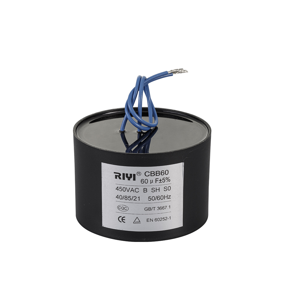
A CBB60 capacitor is a film-type AC motor run capacitor constructed with a metallized polypropylene film dielectric, housed in a cylindrical plastic case and typically filled with a flame-retardant epoxy or resin. The "CBB" designation refers to the Chinese national standard classification for film capacitors, and "60" identifies the specific sub-type used in AC motor applications. These capacitors are ubiquitous in single-phase induction motors found in water pumps, air compressors, washing machines, pool pumps, and HVAC fans worldwide.
Unlike electrolytic capacitors, which are polarized and used primarily in DC circuits, a CBB60 capacitor is non-polarized and designed to operate continuously on AC lines — typically 50 Hz or 60 Hz mains supply. The two ratings printed on every unit, capacitance in microfarads (µF) and working voltage in volts (V), are not arbitrary labels. They are precise engineering parameters that determine whether the capacitor will function correctly and safely in its intended circuit.
A typical CBB60 capacitor label might read 25µF 450V or 30µF 250V. These two numbers describe completely different physical properties of the component, and changing either one has very different consequences. Treating them as interchangeable — thinking "more is better" or "close enough will do" — is one of the most common and dangerous mistakes made by DIY repair technicians and even some professionals.
What the Capacitance Rating (µF) Actually Controls
Capacitance, measured in microfarads, determines how much electrical charge the capacitor can store and release per cycle. In a single-phase AC motor, the run capacitor's job is to create a phase shift in the auxiliary winding current, which produces the rotating magnetic field needed to keep the motor spinning smoothly under load. The amount of phase shift is directly tied to the capacitance value.
Motor designers calculate the exact µF value required to produce the optimal torque, current draw, power factor, and thermal balance for a specific winding configuration. If you install a CBB60 capacitor with the wrong capacitance, even if the voltage rating is correct, the motor will not operate as intended.
Effects of Using Too Low a Capacitance Value
If you substitute a 20µF capacitor where a 25µF unit is specified (a 20% reduction), the phase shift produced in the auxiliary winding decreases. The practical results include:
- Reduced starting torque — the motor may struggle to start under even moderate loads
- Increased current draw in the main winding, raising operating temperatures
- Vibration and humming as the rotating magnetic field becomes uneven
- Accelerated winding insulation degradation, shortening motor lifespan
- Possible motor stall under load conditions that would normally present no problem
Effects of Using Too High a Capacitance Value
Oversizing capacitance — for example, installing a 35µF capacitor where a 25µF unit belongs — is equally problematic:
- Excessive current flows through the auxiliary winding, which is not designed to handle continuous high current
- The auxiliary winding can overheat and burn out within hours or days of operation
- Power factor deteriorates, increasing electricity consumption without improving output
- Capacitor itself runs hotter than its thermal rating allows, reducing its own service life
- In worst cases, winding insulation failure leads to a shorted motor requiring full replacement
The generally accepted tolerance band for capacitor replacement in motor applications is ±5% to ±10% of the original specified value. Beyond that range, the risks described above become progressively more likely. Always match the µF rating as closely as possible to the original specification.
What the Voltage Rating (V) Actually Controls
The voltage rating of a CBB60 capacitor describes the maximum continuous AC or DC voltage that can be applied across the capacitor's terminals without breaking down the dielectric film. For a CBB60 used in AC motor circuits, the rating is expressed as an AC working voltage — for example, 250VAC or 450VAC.
The dielectric film in a CBB60 capacitor is manufactured to a specific thickness. Thicker film allows higher voltage tolerance but increases the physical size of the capacitor for the same capacitance value. When voltage stress exceeds the rated limit, the dielectric begins to degrade through a process called partial discharge — microscopic electrical arcs that erode the film over time — eventually leading to catastrophic dielectric breakdown.
What Happens When Voltage Rating Is Too Low
Installing a CBB60 capacitor with an insufficient voltage rating is a serious safety hazard. For instance, replacing a 450VAC-rated capacitor with a 250VAC unit on a 230V mains circuit might seem acceptable on paper (230V is below 250V), but in practice:
- Mains voltage fluctuates — in many countries, the nominal 230V can legally spike to 253V or higher during grid disturbances
- Motor circuits produce voltage spikes (transients) during start and stop events that can briefly reach 2–3 times the supply voltage
- The voltage across a run capacitor in a motor circuit is not simply the supply voltage — it is determined by the winding impedances and can be significantly higher than the line voltage
- Dielectric breakdown can cause the capacitor case to rupture, expel hot material, or ignite surrounding materials
This is why manufacturers specify voltage ratings with a safety margin. A 450VAC-rated CBB60 capacitor used on a 230V circuit is working at approximately 50% of its rated voltage — a comfortable safety buffer that accommodates transients and supply fluctuations without stress on the dielectric.
Is It Safe to Use a Higher Voltage Rating?
Unlike capacitance, the voltage rating can be exceeded upward without affecting circuit function, provided the capacitance value remains correct. A 25µF 450VAC capacitor will function identically to a 25µF 250VAC unit in a 230V circuit from an electrical standpoint. The higher-voltage unit simply has a thicker dielectric film and more conservative operating conditions, which typically also means longer service life.
The tradeoff is physical size: a higher-voltage capacitor of the same capacitance will generally be larger and heavier. In applications where the replacement must fit in a constrained enclosure, this matters. In open installations like water pump housings with adequate space, using a higher-voltage replacement is generally acceptable and even preferable.
Rule of thumb: voltage rating can be matched or exceeded, but never reduced below the original specification.
Comparing the Two Ratings Side by Side
The table below summarizes the key differences between capacitance and voltage ratings in the context of CBB60 capacitor replacement:
| Parameter | What It Controls | Can You Go Lower? | Can You Go Higher? | Tolerance |
|---|---|---|---|---|
| Capacitance (µF) | Motor phase shift, torque, current balance | No — causes low torque, overheating | No — causes winding overload, burnout | ±5% to ±10% maximum |
| Voltage (V) | Dielectric stress limit, safety margin | No — risk of dielectric failure, fire | Yes — larger size, longer life | Match or exceed; never reduce |
Common Voltage Ratings for CBB60 Capacitors and Their Applications
CBB60 capacitors are manufactured in several standard voltage ratings, each designed for a specific supply voltage range:
| Rated Voltage | Typical Supply Voltage | Common Applications |
|---|---|---|
| 250VAC | 110V–120V AC | North American household motors, small fans |
| 370VAC | 208V–240V AC | HVAC systems, air conditioners, medium motors |
| 450VAC | 220V–240V AC | Water pumps, pool pumps, washing machines, compressors |
| 500VAC | 380V–415V AC (three-phase derived) | Industrial single-phase motors, high-power pumps |
Note that the 370VAC and 450VAC units are both commonly used on 230V–240V mains. You can substitute a 450VAC unit where a 370VAC is specified (same µF), but not the reverse. The 450VAC part provides a larger safety margin against transient voltages.
Can You Combine Multiple Capacitors to Get the Right µF Value
If the exact µF value is unavailable, some technicians attempt to combine two capacitors in parallel to achieve the target capacitance. Capacitors wired in parallel have their capacitances added together — so two 12.5µF units in parallel yield 25µF, for example.
This approach can work in some situations, but there are important caveats:
- Both capacitors must be rated for the same or higher voltage as the original. Combining a 450VAC with a 250VAC capacitor in parallel is not acceptable — the lower-rated unit becomes the weak link.
- Both units must be genuine AC motor-rated film capacitors (CBB60 type or equivalent). Mixing capacitor types — for example, pairing a CBB60 with an electrolytic — will cause rapid failure or immediate circuit damage.
- Physical space inside motor enclosures is usually limited, making parallel combinations impractical for most pump and appliance applications.
- Parallel capacitors also mean two points of potential failure instead of one, increasing long-term maintenance requirements.
The preferred solution is always to source the correct single capacitor with the matching µF and adequate voltage rating.
How to Read and Verify a CBB60 Capacitor Specification
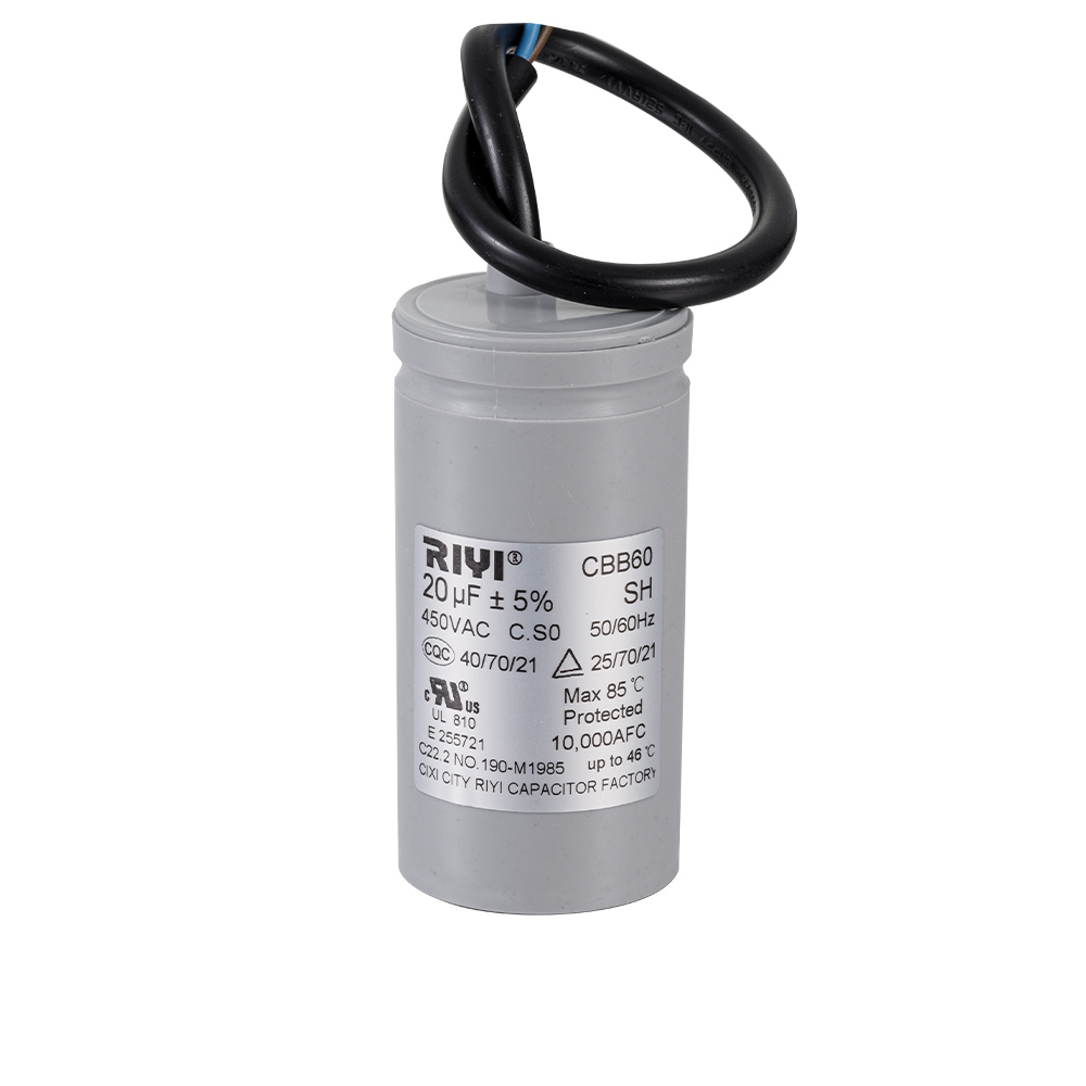
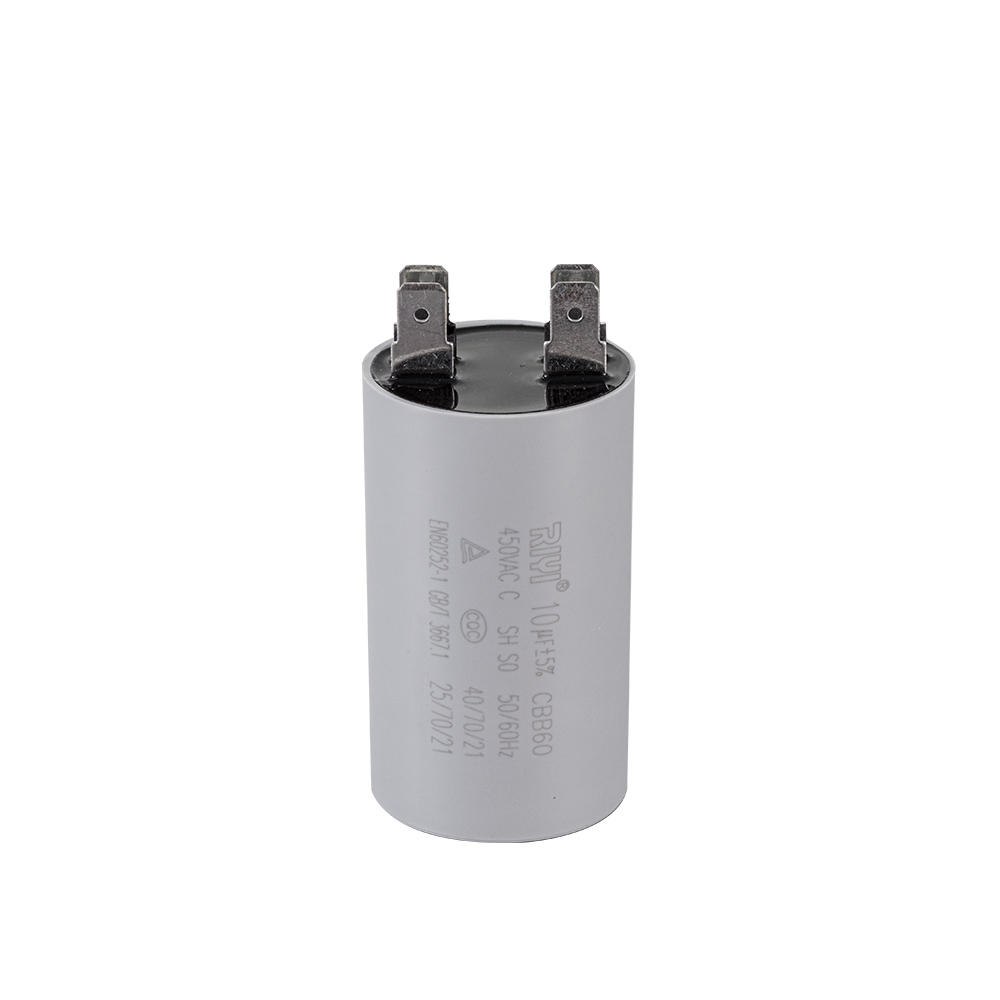
Before purchasing a replacement CBB60 capacitor, you need to correctly read the original unit's markings. Most CBB60 capacitors display the following information on their cylindrical case:
- Capacitance: Printed in µF, such as "25µF," "30µF," or "50µF"
- Voltage: Shown as "450V~" or "450VAC" (the tilde ~ indicates AC rating)
- Frequency: Typically "50/60Hz" indicating suitability for both mains frequencies
- Temperature class: Often "40/70/21" or "40/85/21" per IEC standards, indicating operating temperature range
- Tolerance: Usually ±5% or ±10% printed near the capacitance value
If the labels on your old CBB60 capacitor are illegible — a common problem when the unit has been exposed to heat or moisture — you can find the original specification in the motor's documentation, on the motor nameplate, or by cross-referencing the motor model number with the manufacturer's parts list.
You can also measure capacitance using a digital multimeter equipped with a capacitance function or a dedicated LCR meter. Measure the failed unit if it has not shorted completely — partially degraded capacitors often still show a readable (though reduced) capacitance value. Always verify with specifications rather than relying solely on a measured value from a potentially faulty component.
Why CBB60 Capacitors Fail and How to Extend Their Life
Understanding failure modes helps you choose the right replacement and avoid repeat failures. CBB60 capacitors degrade through several mechanisms:
Thermal Degradation
Heat is the primary enemy of film capacitor dielectrics. Polypropylene film begins to lose its dielectric properties at sustained temperatures above 70°C–85°C, depending on the film grade. Capacitors installed in poorly ventilated motor housings, or near other heat-generating components, age much faster than those operating in cool, open environments. Every 10°C increase in operating temperature approximately halves the expected service life — a well-known rule in capacitor engineering.
Voltage Stress and Partial Discharge
Running a CBB60 capacitor at or above 80% of its rated voltage significantly accelerates partial discharge activity within the dielectric film. Each partial discharge event removes a tiny amount of metallization from the electrodes (the self-healing mechanism inherent to metallized film capacitors), and over thousands of operating hours, the cumulative loss of electrode material results in measurable capacitance loss. When capacitance drops below roughly 85% of its rated value, the motor begins to show performance issues.
Moisture Ingress
CBB60 capacitors used in outdoor applications — pool pumps, irrigation systems, outdoor HVAC units — are exposed to humidity and temperature cycling. Despite their epoxy filling, moisture can penetrate the terminal seals over time, degrading the dielectric film and causing insulation resistance to fall. A correctly rated replacement with an appropriate IP-rated enclosure, and properly sealed terminal connections, will significantly outlast a standard indoor-grade unit in these environments.
Prolonging Service Life in Practice
- Select a replacement with a voltage rating at least 1.5 to 2 times the actual operating voltage — this ensures the capacitor runs well within its comfort zone
- Ensure adequate ventilation around the capacitor and motor housing
- Choose capacitors with a higher temperature rating (85°C class instead of 70°C) for demanding environments
- Inspect capacitors visually every 1–2 years for bulging, cracking, or resin discoloration, which indicate internal stress
- In high-cycle applications (motors that start and stop many times per day), consider proactive replacement every 5 years regardless of apparent condition
Practical Replacement Scenarios and Decisions
Here are several real-world replacement scenarios to illustrate the decision-making process clearly:
Scenario 1: Original is 25µF 450V, replacement available is 25µF 450V
Exact match. Install and proceed. No concerns.
Scenario 2: Original is 25µF 450V, only 25µF 250V is available
Do not install. The voltage rating is insufficient. Wait for a correctly rated replacement. Installing the 250V unit risks dielectric failure and potential fire in a 230V circuit where transients can reach 500V or more.
Scenario 3: Original is 25µF 450V, only 30µF 450V is available
The 20% capacitance increase is outside the safe tolerance range. Do not install as a permanent solution. It may allow the motor to run temporarily in an emergency, but the auxiliary winding is at risk of overheating. Source the correct 25µF unit.
Scenario 4: Original is 25µF 370V, replacement available is 25µF 450V
Acceptable substitution. The voltage rating is higher, which is safe. The 450V unit will be physically larger but will operate correctly and likely last longer in the same circuit.
Scenario 5: Original is 40µF 450V, replacement available is 45µF 450V
The 12.5% overage is borderline. For a non-critical low-duty-cycle application, some technicians would accept this as a temporary measure. For a continuous-duty pump or compressor motor, source the exact value. The risk of winding damage increases measurably at this level of mismatch.
Identifying Quality CBB60 Capacitors: What to Look For
The market for CBB60 capacitors is flooded with products of widely varying quality. A counterfeit or substandard capacitor may bear all the correct markings but use thinner film, lower-grade metallization, or inadequate resin filling — resulting in early failure even under normal operating conditions.
Indicators of a reliable CBB60 capacitor include:
- Compliance markings: CE mark for European standards, UL or cUL listing for North American markets, CQC certification under Chinese national standards
- Consistent physical weight: Heavier units relative to their size generally indicate more complete resin filling and denser dielectric construction
- Clear, legible labeling: Properly specified capacitors display all parameters — capacitance, voltage, frequency, temperature class, and tolerance — with clean printing
- Reputable supply chain: Purchasing from established electrical component distributors rather than anonymous online marketplaces greatly reduces the risk of receiving counterfeit parts
- Measured capacitance at delivery: For critical applications, verify the delivered capacitance with an LCR meter before installation to confirm the unit matches its label
Summary: The Rules for CBB60 Capacitor Rating Substitution
To close out with the clearest possible guidance for anyone sourcing a CBB60 replacement:
- Capacitance (µF) must match the original specification within ±5% to ±10%. Going significantly lower causes poor motor performance and overheating. Going significantly higher overloads the auxiliary winding and causes burnout. This rating is not negotiable.
- Voltage (V) must meet or exceed the original specification. A higher voltage rating is safe and often beneficial for longevity. A lower voltage rating is dangerous and must never be used.
- The two ratings serve completely different engineering purposes and cannot compensate for one another. A higher voltage rating does not offset a wrong capacitance, and a precise capacitance match does not make up for an inadequate voltage rating.
- When in doubt about the original specification, consult the motor manufacturer's documentation rather than guessing or approximating.
- For applications with high ambient temperatures, frequent start-stop cycles, or outdoor exposure, choose a CBB60 capacitor with a higher temperature class and voltage rating than the minimum required — the modest additional cost pays for itself many times over in extended service intervals and avoided motor damage.
Getting these two ratings right is the single most important factor in a successful CBB60 capacitor replacement. The component is inexpensive; the motor it protects is not.


 +86-13600614158
 +86-0574-63223385
 Zonghan Street,Cixi City,Zhejiang Province,China.