
 en
 English

How to Measure a Capacitor: Step-by-Step Multimeter and LCR Meter Guide
Content
- 1 Why Measuring a Capacitor Is Not Optional
- 2 Safety Rules: Discharge First, Measure Second
- 3 Method 1: Digital Multimeter in Capacitance Mode – The Most Practical Way
- 4 Method 2: Analog Multimeter in Resistance Mode – A Quick Health Check
- 5 Method 3: LCR Meter – Precision, ESR, and Dissipation Factor
- 6 How to Interpret Readings: Rated Value and Tolerance
- 7 Measuring Motor Start and Run Capacitors Like a Technician
- 8 Six Measurement Mistakes That Produce Wrong Results
- 9 The Two Numbers That Catch Hidden Failures: ESR and Leakage
- 10 Frequently Asked Questions About Measuring Capacitors
- 10.1 Can I measure a capacitor without removing it from the circuit?
- 10.2 Why does my meter display OL when I measure a capacitor?
- 10.3 What is a good capacitance reading?
- 10.4 How do I discharge a capacitor before measuring it?
- 10.5 What is the difference between testing a start capacitor and a run capacitor?
- 10.6 Can a capacitor with correct capacitance still be bad?
The shortest reliable answer: set your digital multimeter to the capacitance mode (the µF symbol), discharge the capacitor completely, remove it from the circuit, connect the red lead to the positive side and the black lead to the negative side, wait for the reading to stabilize, and compare it with the microfarad value printed on the capacitor case.
A capacitor that measures inside its rated tolerance is electrically healthy. One that reads well below its rated value, reads zero, or produces an out-of-range (OL) display is normally a candidate for replacement. This sequence works for small ceramic capacitors, aluminum electrolytic capacitors, and the larger AC motor-run capacitors used in washing machines, water pumps, and air-conditioner compressors. The details of each step, and the measurement mistakes that produce misleading results, are exactly what this guide covers.
Why Measuring a Capacitor Is Not Optional
Capacitors do not normally fail overnight. A motor-run capacitor rated at 12µF gradually loses capacitance as the metallized film oxidizes, the electrolyte dries out, or the internal connection tab degrades. Some of that drift is expected over a service life of roughly 8 to 10 years. However, once the measured value falls below the lower tolerance limit, the motor it supports draws more current, runs hotter, hums, struggles to start, or stops completely. Measuring the capacitor is the only way to know whether you are replacing a bad part or chasing a circuit fault that will damage the next capacitor too.
Capacitance measurement serves three practical purposes:
- Fault diagnosis: telling a dead capacitor apart from a defective motor winding, start relay, or power-supply stage.
- Verification: testing a brand-new replacement before installation, because capacitors can be mislabeled or damaged during shipping.
- Matching: confirming that the replacement µF rating, voltage class, and tolerance fit the motor or circuit design.
An intermittent failure is often capacitor-related too. A washing machine that stops mid-cycle at random times, a water pump that trips thermal protection after a few minutes, or a refrigerator compressor that buzzes without starting are three classic symptoms frequently caused by a capacitor that still looks physically fine but has drifted below its rated capacitance. Measuring first prevents the classic mistake of replacing a perfectly good capacitor while the real fault sits in the motor start circuit.
Safety Rules: Discharge First, Measure Second
Rule number one: never connect a charged capacitor to a multimeter. Even after equipment is unplugged, a charged capacitor can hold dangerous voltage for a long period. Motor capacitors rated at 370V AC or 450V AC can retain hundreds of volts for several minutes, especially when the appliance has no bleeder resistors. Attaching a charged capacitor to a meter can blow the input fuse, permanently damage the protection circuit, and shock the person holding the leads.
Follow this discharge procedure every time:
- Unplug or disconnect the equipment and wait one to two minutes so internal bleeder resistors can drain the high voltage.
- Connect a 1kΩ to 10kΩ resistor rated at least 5W across the capacitor terminals for 10 to 15 seconds. For capacitors above 50µF, use a 100Ω to 1kΩ resistor and hold it for 20 to 30 seconds.
- Confirm with a voltmeter that the capacitor reads 0V before you touch the terminals with bare hands.
- Small capacitors under 10µF can be discharged by shorting the leads with an insulated screwdriver; the resistor method is still the recommended habit because it avoids sparks and mechanical stress.
Never short a large motor capacitor directly with a screwdriver. The discharge current can weld pits into the tool, splatter molten metal, and crack the capacitor case. The resistor method drains the charge smoothly and safely.
Method 1: Digital Multimeter in Capacitance Mode – The Most Practical Way
A digital multimeter in capacitance mode measures capacitance by charging the capacitor with a known constant current, measuring the resulting rate of voltage rise, and computing the microfarad value from that rate. As described in Fluke’s application guide, this method gives a direct numerical reading with an accuracy of roughly ±1% to ±5% on good instruments, which is sufficient for virtually all field diagnosis. Most modern digital multimeters in the commonly available price range include a µF position, so this method is accessible to nearly everyone.
Step-by-step procedure
- Switch off the equipment and unplug it.
- Remove the capacitor from the circuit. On a circuit board, desolder or lift at least one lead so no parallel components interfere with the reading.
- Discharge the capacitor with the resistor method described in the previous section.
- Turn the multimeter dial to the capacitance mode, usually marked with the µF symbol or two parallel lines.
- If a relative mode (REL or Δ) is available, touch the two probes together, press REL to zero the lead capacitance, then separate the probes. This matters when measuring small values from 1nF to 100nF, because the test leads add a few picofarads of stray capacitance.
- Connect the red probe to the positive terminal (the longer lead of a polarized capacitor) and the black probe to the negative terminal. CBB motor-run capacitors are non-polarized, so orientation does not matter for them.
- Wait for the reading to settle. A 30µF motor capacitor can take several seconds to reach a stable value because the charging current must run long enough for the meter to resolve the capacitance.
- Compare the final reading with the rated value plus tolerance printed on the case.
The table below shows how to interpret what you see on the display.
| Measured result | Diagnosis |
|---|---|
| Within rated value plus or minus tolerance | Healthy capacitor |
| 10% or more below rated value | Aged or degraded; replace in motor applications |
| Near zero, or a short-like reading | Shorted dielectric; replace immediately |
| OL (over range) on the suitable range | Open circuit or value far above range; replace if rated within the selected range |
| Reading keeps climbing and will not settle | Internal leakage or damaged dielectric; treat as suspect |
If the reading is slightly above the rated value, for example 12.8µF on a 12µF ±5% capacitor, the part is still within manufacturing spread and is acceptable. A reading below the tolerance band is the more common aging failure and should prompt replacement.
Method 2: Analog Multimeter in Resistance Mode – A Quick Health Check
If your meter does not have a capacitance mode, the resistance mode still gives a useful health check. Set the selector to the highest resistance range, 10kΩ or above, connect the test leads, and watch the needle movement.
- Good capacitor: the needle jumps toward zero as the capacitor accepts charge, then slowly drifts upward toward the infinity mark.
- Shorted capacitor: the needle stays pinned at or very near zero and never recovers.
- Open capacitor: the needle never moves, and the reading remains at infinity from the very beginning.
- Leaky capacitor: the needle moves briefly, settles at some middle resistance, and never reaches the infinity mark.
The analog resistance test is a pass, fail, or weak indicator only; it cannot give the exact microfarad value. Use it as a quick field check when no capacitance-capable meter is available, but do not make the final decision for a motor repair based only on an analog test.
Method 3: LCR Meter – Precision, ESR, and Dissipation Factor
An LCR meter measures inductance, capacitance, and resistance with substantially higher accuracy and provides extra parameters that a general-purpose multimeter cannot. Typical handheld LCR meters deliver capacitance accuracy between ±0.2% and ±1%, compared with ±3% to ±5% for a digital multimeter. For incoming inspection, production-line verification, and failure analysis of motor capacitors, the LCR meter is the correct tool.
Three things to know when using an LCR meter:
- Test frequency: motor capacitors are specified at mains frequency, 50Hz or 60Hz. LCR meters normally offer 100Hz, 120Hz, 1kHz, and 10kHz. For a motor capacitor, use 100Hz or 120Hz as the closest practical setting, and always record the frequency used because capacitance varies slightly with frequency.
- Dissipation factor: usually written as tan δ or DF, this indicates internal dielectric loss. For metallized polypropylene (CBB) motor capacitors, a dissipation factor below 0.1% at 100Hz is normal. A sharply higher value suggests the film dielectric has deteriorated.
- Equivalent series resistance: ESR is the real resistive loss inside the capacitor at the test frequency. A 20µF motor-run capacitor should show an ESR of a few hundred milliohms or less at 100Hz. If ESR has climbed while the capacitance still reads within tolerance, the capacitor will heat up under load and fail prematurely.
Use an LCR meter whenever a motor continues to behave abnormally after passing the multimeter capacitance test, or when you need to match an exact value for a bank of capacitors. For an ordinary replacement decision, the digital multimeter is enough.
How to Interpret Readings: Rated Value and Tolerance
Capacitance tolerance is the allowed spread of the nominal value at the time of manufacture. IEC 60384-1 defines the standard tolerance classes used across the industry, including ±5%, ±10%, and ±20%. A capacitor marked 20µF ±10% is acceptable if it measures between 18µF and 22µF when new. However, the tolerance band is not a service-life guarantee: after years of AC stress, the same capacitor can drift below 18µF even though it was within tolerance when shipped from the factory.
For motor circuits, the practical rule is stricter than the printed tolerance: if a run capacitor has lost about 10% of its rated capacitance, starting torque drops noticeably and running current rises. Replace it. The printed tolerance reflects the manufacturing process spread at the factory, not the acceptable aging limit.
| Capacitor family | Typical tolerance | Acceptable range for a 10µF part |
|---|---|---|
| CBB film motor capacitors (CBB60, CBB61, CBB65) | ±5% | 9.5µF to 10.5µF |
| General-purpose film capacitors | ±10% | 9.0µF to 11.0µF |
| Aluminum electrolytic capacitors | ±20% | 8.0µF to 12.0µF |
| Class 2 ceramic capacitors (X7R) | −20% to +80% | 8.0µF to 18.0µF |
For best measurement consistency, measure at room temperature between 20°C and 25°C and compare readings taken with the same instrument and the same test frequency.
Measuring Motor Start and Run Capacitors Like a Technician
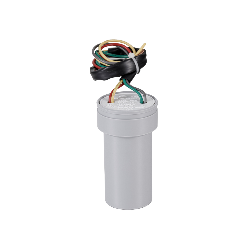
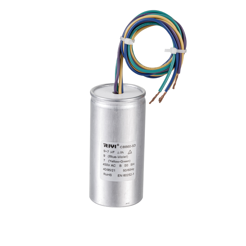
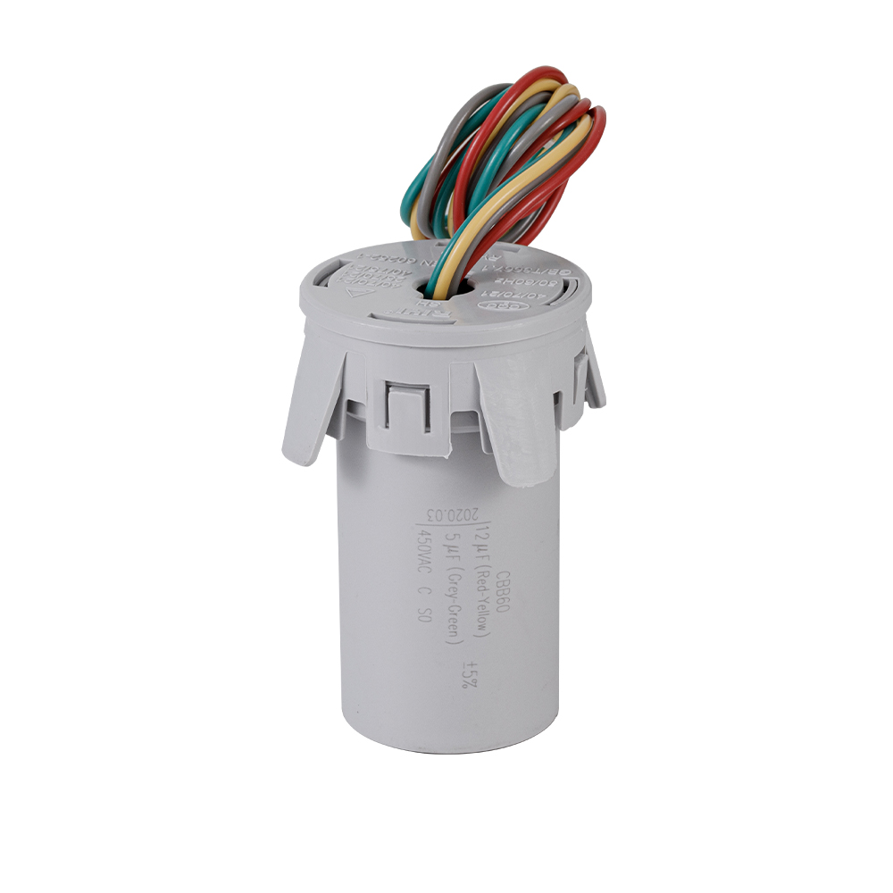
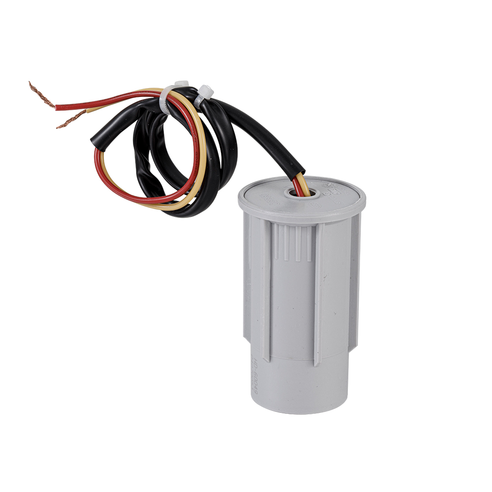
Motor capacitors deserve their own measurement routine because they work under continuous mains-voltage AC stress and their dominant failure mode is gradual capacitance loss. Single-phase motors in washing machines, water pumps, ceiling fans, refrigerator compressors, cooling fans, and air conditioners use two capacitor families.
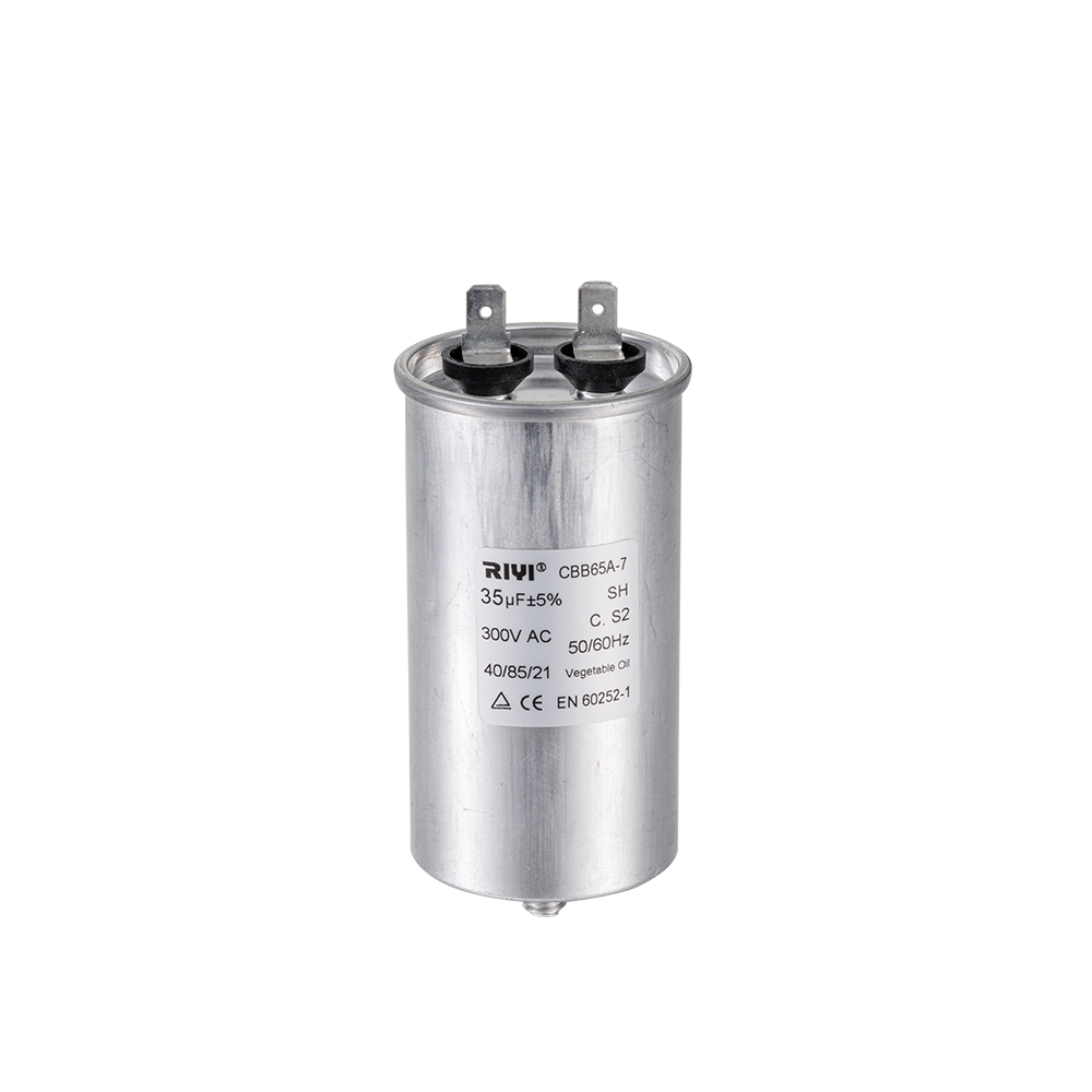
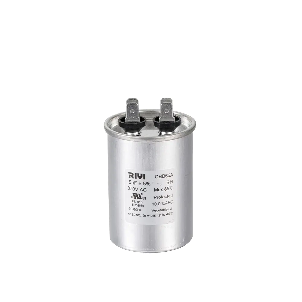
- Run capacitors stay in the circuit the whole time the motor runs. Typical values are 2µF to 60µF, with voltage ratings from 250V AC to 500V AC. Common examples are the round aluminum-case CBB60 type in water pumps, the square CBB61 type in ceiling fans, and the sealed CBB65 type with an explosion-proof aluminum case in air-conditioner compressors.
- Start capacitors engage only during startup. They usually have much larger capacitance values, often from 70µF to several hundred microfarads, and are frequently electrolytic types with wider tolerance. They must be measured after full discharge because their lower internal resistance can deliver a far more energetic discharge.
Field measurement routine
- Inspect the case before measuring. A bulged safety vent, an oil leak along the seam, or a burnt terminal makes the capacitor a replacement candidate even before the multimeter is switched on.
- Disconnect one wire so the capacitor is fully isolated from the motor windings.
- Discharge through a resistor for at least 10 seconds, then confirm 0V across the terminals with a voltmeter.
- Set the meter to capacitance mode and select a range higher than the printed value; for example, the 40µF or 200µF range for a 30µF capacitor.
- Read the value after the display settles, then compare it with the label on the capacitor, not with the value printed in the manual, because manufacturers occasionally revise ratings between production batches.
Practical replacement thresholds: for a run capacitor, replace if the measured value is more than 10% below the printed rating or below the lower printed tolerance limit. If the capacitor reads within tolerance but is physically swollen, replace it anyway; the safety vent has already operated once. For a start capacitor, replace if the reading is unstable, if it reads near zero, or if the measured value is more than 20% below the printed rating.
Lighting and power-factor applications, such as CBB80 series compensation capacitors, can be measured with the same discharge and microfarad procedure, although capacitance is not the only performance parameter; dissipation factor matters just as much for power-factor correction duty.
Six Measurement Mistakes That Produce Wrong Results
- Measuring in-circuit. While the capacitor is still connected, other components such as resistors, motor windings, diodes, or a second capacitor create parallel paths that distort the result. Remove at least one lead before measurement.
- Measuring a charged capacitor. Residual voltage changes the result and can damage the meter. Discharge first and confirm 0V.
- Selecting the wrong range. A value larger than the selected range displays OL, and a value much smaller reads inaccurately. Start with the highest range and step down until the reading occupies a comfortable portion of the scale.
- Reading too early. Large capacitors take seconds to charge in the meter test circuit. Read the value only after the display stabilizes.
- Touching both probes together during the measurement shorts the test current and produces a false near-zero result.
- Ignoring test frequency. Capacitance of film capacitors at 100Hz, 1kHz, and 10kHz differs slightly because of dielectric absorption. When using an LCR meter, pick the frequency that matches the application: 100Hz or 120Hz for mains-frequency motor capacitors.
Any one of these mistakes can turn a good capacitor into a false failure or a bad capacitor into a false success. The routine that avoids them all takes only a minute longer.
The Two Numbers That Catch Hidden Failures: ESR and Leakage
Here is an example that happens more often than most technicians expect: a capacitor measures exactly 30.2µF against a 30µF rating, yet the compressor still starts slowly and trips thermal overload. The missing piece of information is internal resistance. A real capacitor behaves as an ideal capacitor in series with a small resistance (ESR) and in parallel with a high insulation resistance. When the foil connection or the dielectric degrades, ESR rises while the total capacitance may change very little.
ESR measurement
Use an LCR meter or a dedicated ESR meter. For CBB film motor capacitors, typical ESR at 100Hz is below about 0.5Ω. If ESR is much higher, for example above 1Ω for a 20µF capacitor, the capacitor will dissipate heat under load even when the capacitance appears normal, so replacement is justified. For small electrolytic capacitors in power supplies, ESR above 1Ω usually means replacement; values vary with capacitance and voltage, so compare with the manufacturer’s datasheet.
Leakage test
Set the multimeter to the highest resistance range, connect it to the discharged capacitor, and watch the final resistance after 30 to 60 seconds. A healthy large capacitor settles in the high hundreds of kilo-ohms or in the megohm range; a leaky capacitor settles lower and keeps drifting downward. For AC film capacitors in the 400V AC class, insulation resistance of hundreds of megohms is the normal condition.
Combine these two electrical checks with a simple visual inspection. A popped safety vent, a darkened PCB under the capacitor, or the smell of burnt electrolyte all indicate replacement, regardless of what the meter says.
Frequently Asked Questions About Measuring Capacitors
Can I measure a capacitor without removing it from the circuit?
In most cases, no. Parallel components create alternate paths that change the reading. Remove or lift one lead so the capacitor is isolated. Some multimeters offer an in-circuit capacitance mode, but accuracy depends on how dominant the capacitor value is compared with surrounding components; treat such readings as indicative rather than final.
Why does my meter display OL when I measure a capacitor?
OL means over range. Either the capacitor is open, its capacitance is larger than the selected range, or the leads are not making proper contact. Select a higher range, check the probe connections, discharge the capacitor again, and repeat the measurement.
What is a good capacitance reading?
A reading inside the printed tolerance band, measured at room temperature on a stable and settled display. For motor capacitors, the reading should also be within about 10% of the printed value. A reading slightly above rated is normal; a reading below the band indicates aging.
How do I discharge a capacitor before measuring it?
Disconnect power, wait a minute, connect a 1kΩ to 10kΩ resistor across the terminals for 10 to 15 seconds, longer for capacitors above 50µF, then verify 0V with a voltmeter. Use a resistor rated 5W or higher for motor capacitors.
What is the difference between testing a start capacitor and a run capacitor?
Run capacitors are film types designed for continuous AC duty and low dissipation; they should measure close to the printed value at any time. Start capacitors are energized only briefly, often have much larger values and wider tolerance, and are usually tested while fully discharged and isolated. If the value is unstable or near zero, replace the part.
Can a capacitor with correct capacitance still be bad?
Yes. High ESR, high dissipation factor, leakage current, or physical damage such as a bulging case or an opened safety vent can make a capacitor fail in service even when the microfarad reading is within tolerance. Evaluate capacitance first, then confirm with ESR or leakage checks and physical condition.
The complete capacitor measurement workflow – discharge, isolate, measure microfarads, compare with the rated tolerance, then confirm with ESR or a physical check – takes less than five minutes and prevents most repeated electrical failures in motor-driven appliances.
- A capacitor that looks good on the outside can still be bad: swollen cases, burnt terminals, and leaking seams are decisive evidence on their own.
- A capacitor that reads low on capacitance is already degraded: replace it before it weakens a motor further.
- Safety is always first: discharge, isolate, confirm 0V, then measure.
With those habits in place, your multimeter will give you a trustworthy answer every time.


- Tel: +86-13600614158
- E-mail: mina@cxriyi.com
- Address: Zonghan Street,Cixi City, Zhejiang Province, China.
Copyright © CIXI RIYI CAPACITOR FACTORY
All Rights Reserved.
 custom air conditioner capacitor for sale
China Ac Motor Capacitor Factory