
 en
en
 English
104J Capacitor Value Explained: CBB60 Capacitor Guide
Content
- 1 What Does 104J Mean on a Capacitor
- 2 Decoding the Three-Digit and Letter System in Full
- 3 How CBB60 Capacitors Relate to This Value System
- 4 Matching Capacitor Value to Application
- 5 Comparing 104J Style Capacitors with CBB60 Capacitors Side by Side
- 6 Testing and Verifying Capacitor Values
- 7 Factors That Shorten or Extend Capacitor Working Life
- 8 Installation and Wiring Considerations for CBB60 Capacitors
- 9 Frequently Asked Questions
- 9.1 What is the actual microfarad value of a 104J capacitor
- 9.2 Can a CBB60 capacitor be marked with a similar three-digit code
- 9.3 Is a higher tolerance letter always better than J
- 9.4 Why do CBB60 capacitors need an AC voltage rating instead of a DC rating
- 9.5 What happens if the wrong CBB60 value is installed on a motor
- 9.6 How often should a CBB60 capacitor be checked
- 9.7 Can a 104J capacitor be used in place of a CBB60 capacitor
- 9.8 Does a larger CBB60 microfarad value always mean stronger motor starting performance
- 9.9 What does the self-healing property of a CBB60 capacitor actually protect against
- 9.10 Why do two capacitors with the same 104J code sometimes have different physical sizes
What Does 104J Mean on a Capacitor
104J printed on a capacitor body means the component has a capacitance of 100,000 picofarads, which equals 0.1 microfarads, with a tolerance of plus or minus 5 percent. The first two digits, 10, are the significant figures, the third digit, 4, tells you how many zeros to add after those two figures when the result is expressed in picofarads, and the letter J is the tolerance code that follows the numeric part. This three-digit-plus-letter marking system exists because small ceramic disc capacitors, monolithic multilayer capacitors, and many film capacitors have bodies too small to print a full decimal value with a unit symbol in readable text, so manufacturers adopted a compact shorthand instead.
Once the pattern is understood, reading any similar marking becomes routine rather than confusing. A 103J capacitor is 10,000 pF or 0.01 microfarads, a 224J capacitor is 220,000 pF or 0.22 microfarads, and a 474J capacitor is 470,000 pF or 0.47 microfarads. The tolerance letter changes the guaranteed accuracy range around that nominal figure rather than the nominal value itself, so a 104K and a 104J both measure close to 0.1 microfarads on a fresh, undamaged part, but the K version allows a wider plus or minus 10 percent spread while the J version is held to a tighter plus or minus 5 percent band.
This coding habit is not unique to one factory or one country. It traces back to a shared industry convention that spread because it let manufacturers stamp a value onto a component using only four characters, regardless of whether that component ended up in a television, a washing machine control board, a power supply, or an industrial sensor. Anyone working with electronics on a regular basis eventually memorizes the handful of common three-digit codes simply through repeated exposure, the same way someone working with plumbing fittings memorizes common pipe diameters without needing to look each one up.
Decoding the Three-Digit and Letter System in Full
The coding convention on 104J style capacitors follows the same logic used across most disc, ceramic, and small film capacitors sold globally. Manufacturers rely on this shorthand because stamping five or six characters onto a component the size of a grain of rice is far easier than printing a full decimal value with a unit symbol, and because a standardized system means a technician trained on one brand's parts can read another brand's parts without relearning anything.
| Printed Code | Value in pF | Value in µF | Typical Use |
|---|---|---|---|
| 101J | 100 pF | 0.0001 µF | High-frequency bypass, RF tuning |
| 102J | 1,000 pF | 0.001 µF | Noise filtering, RF coupling |
| 103J | 10,000 pF | 0.01 µF | Decoupling in logic circuits |
| 104J | 100,000 pF | 0.1 µF | General bypass, power supply smoothing |
| 154J | 150,000 pF | 0.15 µF | Snubber networks, EMI suppression |
| 224J | 220,000 pF | 0.22 µF | Motor start assist, timing circuits |
| 334J | 330,000 pF | 0.33 µF | Audio filtering, power line coupling |
| 474J | 470,000 pF | 0.47 µF | Audio coupling, snubber networks |
| 105J | 1,000,000 pF | 1 µF | Power supply bulk filtering |
Tolerance letters follow a separate standard from the numeric value, and this is a point that trips up people who are new to reading these markings. J means plus or minus 5 percent, K means plus or minus 10 percent, M means plus or minus 20 percent, F means plus or minus 1 percent, and G means plus or minus 2 percent. In a circuit where timing accuracy or filter cutoff frequency matters, a tighter tolerance like J or F keeps behavior predictable across a production batch, while a looser tolerance like M is acceptable for basic bypass or noise suppression roles where the exact value only needs to fall within a broad range rather than hit a precise target.
Why the Third Digit Is a Multiplier and Not Just Another Figure
A common point of confusion is treating all three digits as if they were significant figures, which leads to a wrong reading. The correct approach is to treat only the first two digits as the base number, then use the third digit purely as a power-of-ten multiplier applied to picofarads. For 104, the base number is 10 and the multiplier is 10 to the fourth power, giving 10 multiplied by 10,000, which equals 100,000 picofarads. Applying that same logic to 475 gives a base of 47 and a multiplier of 10 to the fifth power, producing 4,700,000 picofarads, or 4.7 microfarads, a value sometimes seen on larger film capacitors used in power electronics.
Voltage Ratings Printed Alongside the Code
Many capacitors carrying a 104J style code also carry a separate voltage rating printed nearby, commonly 50V, 100V, 250V, 400V, or 630V for film types. This voltage figure is the maximum working voltage the dielectric can tolerate continuously without breaking down, and it is entirely independent of the capacitance value itself. A 104J capacitor rated for 50V and a 104J capacitor rated for 400V store the identical 0.1 microfarad charge at a given voltage, but the 400V version uses a thicker or different dielectric material to survive higher continuous stress, which is why it is physically larger and generally costs more to produce.
How CBB60 Capacitors Relate to This Value System
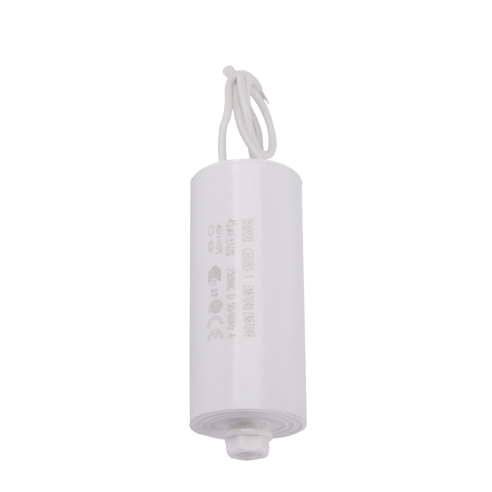
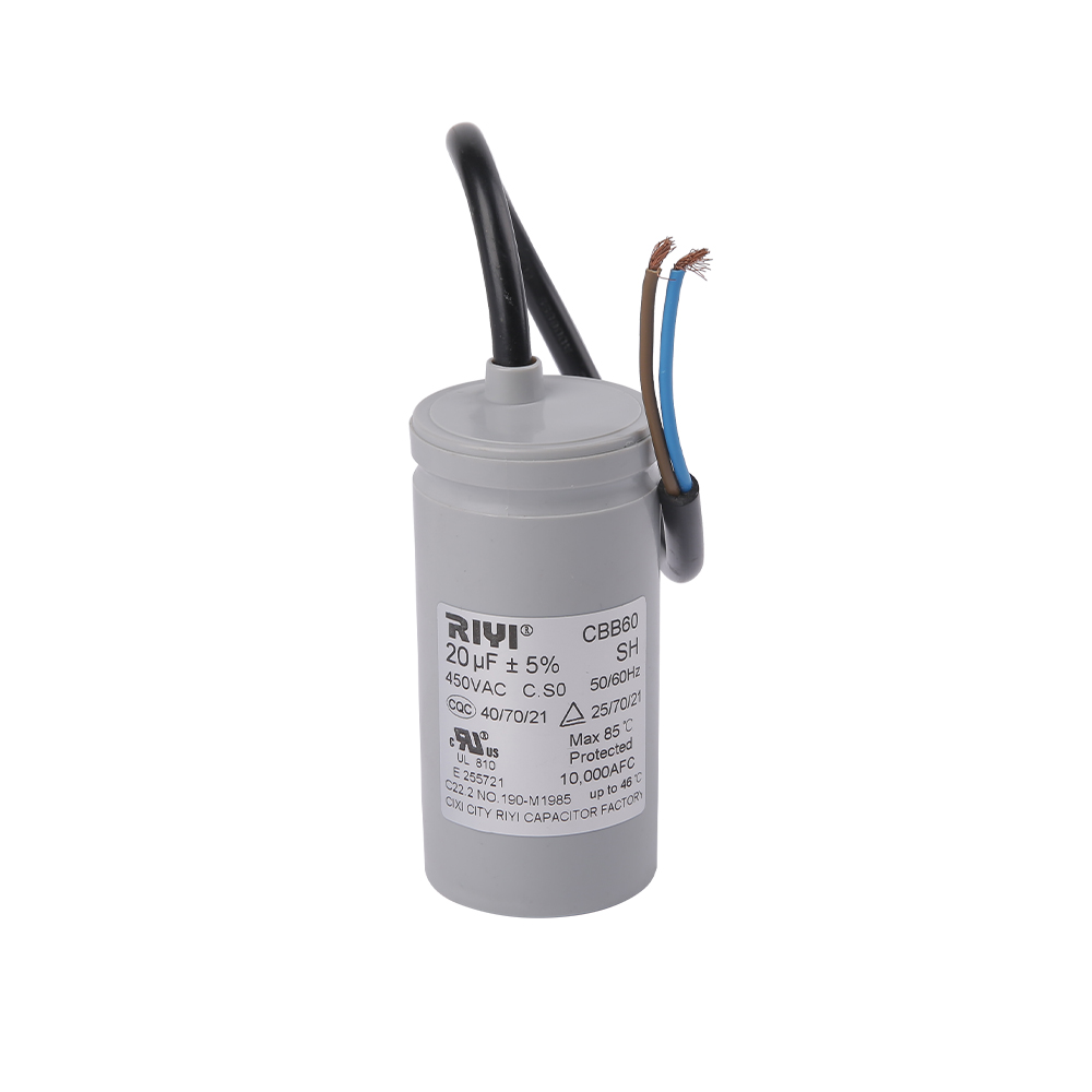
A CBB60 capacitor is a metallized polypropylene film capacitor built specifically for running AC induction motors, most commonly the single-phase motors found in water pumps, fans, compressors, and other rotating equipment. Unlike a small ceramic disc marked 104J, a CBB60 capacitor is a larger cylindrical or oval component rated for continuous AC voltage, typically 250V or 450V, and it is labeled directly in microfarads rather than the three-digit pF code, because there is enough surface area on the case to print the full value along with voltage rating, tolerance, and frequency information.
Even though CBB60 units skip the shorthand coding, the underlying capacitance math is identical to the small coded parts. A CBB60 capacitor rated at 25 microfarads stores the same type of charge relationship as a 0.1 microfarad ceramic capacitor, just at a scale roughly 250 times larger, and built with a dielectric and construction suited to sustained AC ripple current rather than brief DC filtering pulses. Anyone comparing a small signal capacitor coded 104J against a CBB60 motor run capacitor is really comparing two different jobs: signal conditioning at the microfarad-fraction level versus motor phase-shifting at tens of microfarads.
Typical CBB60 capacitance values found in motor nameplates and pump manuals range from 1.5 µF up through 50 µF, with common stock values at 4 µF, 6 µF, 8 µF, 10 µF, 16 µF, 20 µF, 25 µF, 30 µF, 35 µF, 40 µF, and 45 µF. Selecting the correct CBB60 value for a motor is not optional guesswork; the capacitor value is chosen by the motor manufacturer based on winding design, and swapping in a mismatched value changes starting torque, running current, and heat buildup in the motor windings.
Physical Construction of a CBB60 Capacitor
The internal structure of a CBB60 capacitor uses thin polypropylene film with a metallized aluminum or zinc layer deposited directly onto its surface, wound into a compact cylinder rather than stacked as flat plates. This metallized film construction gives the capacitor a self-healing property: if a tiny weak spot in the dielectric breaks down under voltage stress, the localized heat vaporizes the thin metal layer right around that spot, isolating the fault instantly without taking the whole capacitor out of service. This is one of the reasons metallized film capacitors like the CBB60 are preferred for continuous AC motor duty over other dielectric types that lack this self-clearing behavior.
The outer case is typically a hard plastic shell filled with an epoxy resin or a similar potting compound, which seals out moisture and provides mechanical stability against the vibration a running motor produces. Two or three terminal lugs extend from the top, sized to accept standard spade connectors, and many CBB60 units also include a built-in pressure-relief mechanism in the case design, so that if internal pressure builds up from a fault condition, the case vents in a controlled way rather than rupturing unpredictably.
Matching Capacitor Value to Application
Choosing between a small coded capacitor and a CBB60 style run capacitor comes down to the electrical role the component plays, not personal preference. The list below lines up the two capacitor families against the situations where each one is the correct choice.
- Signal-level filtering, decoupling, and timing on printed circuit boards call for coded ceramic or film capacitors like 104J, since these roles need small, stable values in a compact footprint.
- Motor phase-shifting for single-phase AC motors calls for a CBB60 or equivalent run capacitor, since these roles need a large capacitance rated for continuous line voltage and ripple current.
- Any capacitor placed across an AC line, even briefly, should carry an AC voltage rating with margin above the supply voltage, which is why CBB60 units are rated 250V or 450V rather than the lower DC voltage ratings common on small ceramic parts.
- Replacement capacitors should match the original microfarad value within the stated tolerance band, since substituting an undersized or oversized value shifts motor phase angle and can shorten motor life.
- Environments with high ambient heat or continuous duty cycles favor CBB60 capacitors with a higher temperature rating, since sustained heat is one of the main factors that gradually reduces film capacitor lifespan.
Field data collected by motor repair technicians and referenced in general appliance service literature consistently shows that a run capacitor value drifting more than 10 percent below its rated microfarad figure correlates with noticeably reduced starting torque and higher operating current on single-phase compressor and pump motors, which is one reason CBB60 capacitors are usually specified with tighter tolerance bands such as plus or minus 5 percent rather than the looser bands acceptable on general-purpose signal capacitors.
Reading a Motor Nameplate for the Correct Value
Most single-phase motors that require a run capacitor list the exact microfarad value and voltage rating directly on the nameplate, often shown as something like "Cap 20uF 450V". When the nameplate is missing or worn away, the original capacitor itself, if it is still legible, is the next best reference. If neither is available, matching against the horsepower and voltage rating of the motor using a manufacturer's cross-reference chart is the standard fallback approach, since motor winding designs at a given horsepower and voltage tend to cluster around a narrow range of suitable capacitance values.
Comparing 104J Style Capacitors with CBB60 Capacitors Side by Side
Placing the two capacitor families next to each other makes the practical differences easy to see at a glance, even though both ultimately store electrical charge using the same basic physics.
| Attribute | 104J Style Capacitor | CBB60 Capacitor |
|---|---|---|
| Typical capacitance | Fractions of a microfarad | 1.5 to 50 microfarads |
| Primary duty | Signal filtering, decoupling | Motor phase-shifting, running assist |
| Voltage rating style | DC working voltage, low to moderate | Continuous AC voltage, 250V or 450V |
| Labeling method | Three-digit plus letter code | Full microfarad value printed on case |
| Physical size | Small, board-mounted | Larger cylindrical case with lug terminals |
| Duty cycle exposure | Intermittent, low ripple current | Continuous, sustained ripple current |
The distinction matters most when someone is troubleshooting equipment and finds two unfamiliar capacitors side by side, one small and coded, one larger and printed in plain microfarads. Recognizing which family a component belongs to immediately narrows down what role it plays and what kind of replacement part is appropriate, rather than assuming both parts serve interchangeable functions simply because both are labeled capacitors.
Testing and Verifying Capacitor Values
Confirming that a capacitor still matches its printed value, whether it carries a 104J style code or a CBB60 label, is a quick check with the right meter. A digital multimeter with a capacitance range, or a dedicated LCR meter, reads the actual stored capacitance directly. The component should first be fully discharged, since a charged capacitor can damage a meter or give a false reading.
Steps for a Basic Capacitance Check
Disconnect the capacitor from the circuit or motor completely before testing, since a capacitor still wired into a live circuit will give inaccurate readings and can present a shock hazard from stored charge. Discharge the capacitor by bridging its terminals briefly with an insulated resistor lead rather than a bare screwdriver, since a direct short can pit the terminals. Set the meter to the capacitance function, connect the leads to the two terminals, and compare the displayed reading against the printed value, allowing for the stated tolerance percentage.
A 104J capacitor reading anywhere between 0.095 µF and 0.105 µF sits inside its plus or minus 5 percent window and is functioning normally. A CBB60 capacitor printed as 25 µF that reads below roughly 20 µF has likely degraded and should be replaced, since a motor run capacitor that has lost more than 20 percent of its rated capacitance is a common cause of motors that hum but fail to start, or that start slowly under load.
Recognizing Physical Warning Signs Before Testing
A visual inspection often reveals problems before a meter reading confirms them. A CBB60 capacitor with a bulging or swollen case top, visible cracking along the seams, or a leaking dark residue around the terminals has almost certainly failed internally, and testing it further offers little additional information beyond confirming it needs replacement. Small ceramic capacitors coded 104J rarely show visible swelling since their construction differs from film types, but cracked ceramic bodies or discolored solder joints on the board around the part are useful visual clues that something in that area has overheated.
Interpreting Readings That Fall Outside Tolerance
A reading that drifts high, rather than low, on a film capacitor is less common but can still occur, and it generally points toward a meter calibration issue or a measurement taken while residual charge was still present rather than an actual increase in capacitance, since capacitors do not gain capacitance through normal aging. A reading that drifts low is the far more frequent pattern and reflects gradual dielectric degradation, moisture ingress, or the cumulative effect of the self-healing clearing events described earlier, each of which slightly reduces the effective plate area over the component's working life.
Factors That Shorten or Extend Capacitor Working Life
Both capacitor families age due to the same underlying stresses, even though the timescales and failure symptoms differ because of their different jobs and operating environments.
Heat
Elevated ambient temperature is consistently identified as the single largest factor shortening film and ceramic capacitor life, since heat accelerates the chemical breakdown of the dielectric material and any internal binding compounds. A CBB60 capacitor mounted directly against a hot compressor housing will age faster than an identical part mounted with an air gap and some ventilation, even if both see the same electrical load.
Voltage Stress
Running a capacitor consistently near or above its rated voltage compresses its working life significantly compared to running it with margin below that rating. This is why selecting a CBB60 rated for 450V on a nominal 220V or 240V supply line, rather than cutting the margin close with a 250V-rated part, is a common practice in regions where line voltage fluctuates or occasionally spikes.
Ripple Current and Duty Cycle
Capacitors used in continuous duty, such as a CBB60 on a motor that runs for hours at a stretch, experience more cumulative ripple current heating than a capacitor used only in brief, intermittent bursts. This is one reason motor run capacitors are physically larger relative to their capacitance value than small signal capacitors of a similar microfarad rating, since the larger case surface area helps dissipate the heat generated by sustained current flow.
Humidity and Contamination
Moisture that finds a path into the capacitor body, whether through a damaged case seal or a manufacturing defect, accelerates dielectric breakdown and can lead to a sudden rather than gradual failure. Sealed epoxy-filled cases on CBB60 capacitors exist specifically to slow this pathway, which is why a cracked or damaged case is treated as a strong indicator that a capacitor should be replaced even if it still tests within tolerance at that moment.
Installation and Wiring Considerations for CBB60 Capacitors
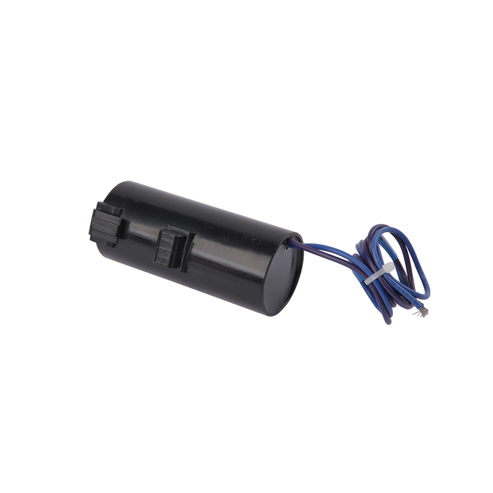
Correct installation affects both performance and working lifespan just as much as selecting the right microfarad value. A CBB60 capacitor is generally wired in parallel with the motor's start or run winding circuit, and the terminal layout on the case, whether it has two or three lugs, determines how it connects into single-value or dual-value motor applications.
Mounting Orientation and Location
Mounting a CBB60 capacitor in a location shielded from direct sun exposure and away from other heat-generating components extends its practical working life measurably compared to mounting it against a hot surface with no airflow. Vertical mounting with the terminals facing downward is a commonly recommended orientation in equipment manuals, since it reduces the chance of moisture or condensation pooling around the terminal connections.
Terminal Connections
Spade connectors should fit snugly onto the capacitor terminals without excessive play, since a loose connection generates localized heating at the contact point every time current flows, gradually degrading both the connector and the terminal lug. Wire gauge should match the expected current draw of the circuit, and connections should be mechanically secure enough to withstand the vibration a running motor produces over months or years of service.
Replacement Value Substitution Range
When an exact replacement value is not available, a commonly referenced practical guideline allows a substitute CBB60 value within about plus or minus 10 percent of the original rated microfarad figure without materially affecting motor performance, though staying as close as possible to the original nameplate value remains the preferred approach whenever that exact part can be sourced.
Frequently Asked Questions
What is the actual microfarad value of a 104J capacitor
A 104J capacitor measures 0.1 microfarads, equivalent to 100,000 picofarads, with a tolerance of plus or minus 5 percent around that nominal value.
Can a CBB60 capacitor be marked with a similar three-digit code
Most CBB60 capacitors print the full microfarad value directly on the case rather than using the three-digit pF shorthand, because the larger case has room for plain text labeling, along with voltage rating and tolerance.
Is a higher tolerance letter always better than J
No. A tighter tolerance like F or J means the actual value stays closer to the nominal figure, which matters for timing and filter circuits, but for general bypass duty a looser tolerance such as K or M is perfectly acceptable and often less costly.
Why do CBB60 capacitors need an AC voltage rating instead of a DC rating
CBB60 capacitors sit directly across the AC line while the motor runs, so they experience continuous alternating voltage and ripple current, which requires a dielectric and construction rated for sustained AC duty rather than the brief DC pulses a small ceramic capacitor typically handles.
What happens if the wrong CBB60 value is installed on a motor
An incorrect microfarad value changes the phase angle between the motor windings, which can reduce starting torque, increase running current, and raise operating temperature, shortening the working life of the motor.
How often should a CBB60 capacitor be checked
There is no universal fixed interval, since service life depends on ambient temperature, run time, and voltage stability, but checking capacitance whenever a motor shows slow starting, humming, or tripped overload protection is a reasonable practical trigger point.
Can a 104J capacitor be used in place of a CBB60 capacitor
No, the two are not interchangeable. A 104J capacitor holds only 0.1 microfarads and is rated for low signal-level voltage, while a motor requires tens of microfarads at a continuous AC voltage rating far beyond what a small coded capacitor is built to handle.
Does a larger CBB60 microfarad value always mean stronger motor starting performance
Not necessarily. Motor windings are designed around a specific capacitance value chosen by the manufacturer, and installing a value significantly larger than specified can overheat the winding and the capacitor itself rather than improve performance, so matching the nameplate value is the safer approach rather than assuming bigger is better.
What does the self-healing property of a CBB60 capacitor actually protect against
It protects against small, localized dielectric weak points turning into a complete short circuit, since the brief clearing event isolates the fault to a tiny area instead of letting it propagate across the whole film layer, which is one of the reasons metallized film construction is favored for continuous AC motor duty.
Why do two capacitors with the same 104J code sometimes have different physical sizes
Physical size differences between two 104J capacitors usually come down to a different voltage rating or a different dielectric material, since both factors affect how thick the dielectric layer needs to be, even though the capacitance value and tolerance printed on the case remain identical.

- Tel: +86-13600614158
- E-mail: mina@cxriyi.com
- Address: Zonghan Street,Cixi City, Zhejiang Province, China.
Copyright © CIXI RIYI CAPACITOR FACTORY
All Rights Reserved.
 custom air conditioner capacitor for sale
China Ac Motor Capacitor Factory
custom air conditioner capacitor for sale
China Ac Motor Capacitor Factory