 简体中文
简体中文 English
 Español
 عربى
عربىContent
- 1 What Does uF Mean on a Capacitor?
- 2 The Farad: Why We Use Microfarads Instead
- 3 Capacitance Unit Conversion: uF, nF, and pF Explained
- 4 CBB60 Capacitor: The Most Common uF-Rated Motor Capacitor
- 5 How Capacitance (uF) Affects Motor Performance
- 6 How to Read uF Values on Capacitor Labels
- 7 Voltage Ratings and Why They Matter as Much as uF
- 8 Types of Capacitors and Their Typical uF Ranges
- 9 Real-World Applications Where uF Ratings Are Critical
- 10 How to Test a Capacitor's Actual uF Value
- 11 How to Select the Right uF-Rated CBB60 Capacitor for Replacement
- 12 How Capacitors Lose uF Over Time
- 13 CBB60 vs. Other Motor Capacitor Types: A uF Comparison
- 14 Frequently Asked Questions About uF Capacitor Meaning
- 14.1 What does uF mean on a capacitor?
- 14.2 Can I replace a capacitor with a higher uF value?
- 14.3 Is a CBB60 capacitor the same as a run capacitor?
- 14.4 How do I know what uF capacitor my motor needs?
- 14.5 What happens if I use a capacitor with the wrong uF rating?
- 14.6 What is the difference between uF, nF, and pF?
- 14.7 How long does a CBB60 capacitor last?
- 14.8 Why is the µ symbol sometimes written as u in capacitor labeling?
- 14.9 Can a capacitor with the right uF rating but wrong voltage rating be used?
- 14.10 What is the capacitance tolerance for CBB60 capacitors?
What Does uF Mean on a Capacitor?
The abbreviation uF stands for microfarad, a unit used to measure a capacitor's electrical capacitance — its ability to store electric charge. One microfarad equals one-millionth of a farad (1 µF = 10⁻⁶ F). In everyday electrical and electronic components, the farad itself is an enormous unit, so most practical capacitors are rated in microfarads (µF or uF), nanofarads (nF), or picofarads (pF).
When you see a label like 10uF 450V printed on a capacitor body, it tells you two critical things: the component can store charge at a capacitance of 10 microfarads, and it is rated to handle voltages up to 450 volts. Understanding what those numbers mean — and choosing the right values — is essential for anyone working with motors, HVAC systems, home appliances, or industrial machinery.
The symbol µF (Greek letter mu + F) and uF (Latin letter u + F) are interchangeable in practice. The "u" substitution became widespread because the µ symbol was difficult to type on early keyboards and is still absent from many standard typewriter-style labels. Both notations appear on capacitor markings worldwide, and they always mean exactly the same thing: microfarad.
The Farad: Why We Use Microfarads Instead
The farad (F) was named after English physicist Michael Faraday and is the SI unit of capacitance. By definition, a capacitor has a capacitance of one farad when one coulomb of charge changes the voltage across it by one volt. In formula form:
C = Q / V
Where C = capacitance in farads, Q = charge in coulombs, V = voltage in volts
One farad is a staggeringly large capacitance for a discrete component. A 1 F capacitor at practical voltage levels would need to be physically enormous — far larger than anything useful in consumer electronics or motors. To put that into perspective, a large electrolytic capacitor used in an audio amplifier's power supply might be 10,000 µF — and that is still only 0.01 farads. The capacitors found in most household appliances and motor-start circuits are typically rated between 1 µF and 100 µF.
This is precisely why microfarads became the dominant unit for practical capacitor specification. The prefix "micro-" denotes 10⁻⁶, meaning:
- 1 µF (uF) = 0.000001 F = 10⁻⁶ F
- 1 nF = 0.001 µF = 10⁻⁹ F
- 1 pF = 0.000001 µF = 10⁻¹² F
For high-frequency circuits such as RF filters and oscillators, nanofarads and picofarads dominate. For motor-run, motor-start, and power-factor correction capacitors — including the widely used CBB60 capacitor — the microfarad range of roughly 1 µF to 100 µF is standard.
Capacitance Unit Conversion: uF, nF, and pF Explained
Confusion between µF, nF, and pF is common, especially when reading datasheets or replacing components. The table below gives a quick reference for converting between common capacitance units:
| Unit | Symbol | Value in Farads | Value in µF | Typical Application |
|---|---|---|---|---|
| Farad | F | 1 | 1,000,000 µF | Supercapacitors / energy storage |
| Millifarad | mF | 0.001 | 1,000 µF | Large electrolytic filters |
| Microfarad | µF / uF | 0.000001 | 1 µF | Motor caps, CBB60, HVAC, appliances |
| Nanofarad | nF | 0.000000001 | 0.001 µF | Audio filters, signal coupling |
| Picofarad | pF | 10⁻¹² | 0.000001 µF | RF circuits, oscillators, antenna tuning |
For motor-running applications, the most important range to understand is 1 µF to 100 µF. A single-phase washing machine motor might use a 12 µF run capacitor. A central air conditioning compressor could require a 35 µF or 45 µF unit. Water pump motors frequently use CBB60 capacitors in the 6 µF to 30 µF range. Knowing how to read and match these values correctly prevents premature equipment failure and inefficient operation.
CBB60 Capacitor: The Most Common uF-Rated Motor Capacitor
The CBB60 capacitor is a metalized polypropylene film capacitor specifically designed for use as a motor-run capacitor in single-phase AC circuits. It is one of the most widely produced and deployed capacitor types in the world, used in water pumps, washing machines, air conditioning units, power tools, and industrial motors. The "CBB" designation is part of the Chinese national standard (GB/T 3667) classification for AC capacitors, where "CBB" indicates a metallized film capacitor and "60" refers to the sub-category for motor-running use.
The uF rating of a CBB60 capacitor is its defining specification. Standard production values for CBB60 capacitors include:
- 2 µF, 3 µF, 4 µF — small single-phase fan motors, circulation pumps
- 6 µF, 8 µF, 10 µF — standard residential water pumps and washing machine motors
- 12 µF, 14 µF, 16 µF — larger washing machines, submersible pumps
- 20 µF, 25 µF, 30 µF — heavy-duty irrigation pumps, compressors
- 40 µF, 50 µF, 60 µF — large industrial motors and HVAC compressors
Voltage ratings for CBB60 capacitors are equally important. The most common voltage classes are 250V AC, 400V AC, and 450V AC. For a 220V–240V AC mains circuit, a 250V AC CBB60 capacitor is the minimum acceptable rating; however, using a 400V AC or 450V AC rated unit provides a higher safety margin against voltage surges, which is why 450V AC CBB60 capacitors are the preferred choice in many export markets and for motors with variable loads.
The self-healing property of the metallized polypropylene film inside a CBB60 capacitor is a key advantage over older paper capacitors. When a localized dielectric breakdown occurs, the metallized layer around the fault point evaporates and isolates the damaged zone, allowing the capacitor to continue functioning. This characteristic is why CBB60 capacitors typically carry a service life rating of 30,000 hours or more at rated conditions, far exceeding oil-impregnated paper capacitors of equivalent uF rating.
How Capacitance (uF) Affects Motor Performance
In a single-phase induction motor, the capacitor creates a phase shift between the main winding current and the auxiliary winding current. This phase difference generates the rotating magnetic field necessary to start and run the motor. The uF value of the capacitor directly determines how much phase shift is produced and therefore how well the motor performs.
What Happens with the Correct uF Rating
When a motor is fitted with a capacitor of exactly the right uF value, the phase shift between main and auxiliary windings approaches 90 degrees — the ideal condition for maximum starting torque and efficient running. The motor draws its rated current, reaches full speed quickly, and maintains stable operation under load. The capacitor's reactive current exactly compensates the inductive reactance of the motor windings, resulting in a power factor close to unity.
What Happens with a Lower-Than-Rated uF Value
Installing a capacitor with a lower uF rating than specified reduces the phase shift angle. The motor may still start but will produce less torque, run hotter, draw more current from the mains, and struggle under load. In severe cases, the motor stalls on startup or hums without rotating. For pumps and compressors where load is applied immediately at startup, an undersized uF capacitor is a common cause of motor burnout.
What Happens with a Higher-Than-Rated uF Value
An oversized capacitor — one with a higher uF value than specified — also creates problems. The phase shift exceeds the optimal angle, causing the motor to run with excessive auxiliary winding current. This increases winding temperature, shortens insulation life, and can cause the motor to vibrate excessively or run at slightly incorrect speed. While an oversized CBB60 capacitor does not immediately destroy a motor, sustained use degrades reliability.
As a practical rule, motor capacitor replacement should use a uF value within ±5% to ±10% of the original specified value. Voltage rating should always meet or exceed the original specification — never substitute a lower-voltage-rated capacitor, even temporarily.
How to Read uF Values on Capacitor Labels
Capacitors are labeled in several different ways depending on their type and manufacturer. Understanding how to decode these labels allows correct identification and replacement.
Directly Printed uF Values
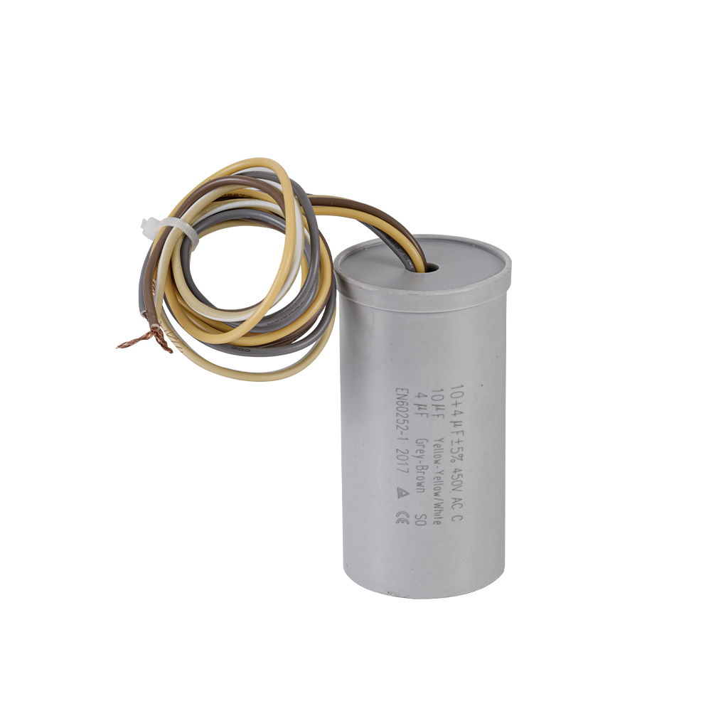
Most motor-run capacitors — including CBB60 capacitors — print the capacitance value directly on the body in microfarads, followed by the voltage rating and frequency rating. A typical CBB60 label might read:
CBB60 — 20µF ±5% — 450VAC — 50/60Hz
This tells you: it is a CBB60 type capacitor, rated at 20 microfarads with a ±5% tolerance, for use on 450V AC circuits at either 50 Hz or 60 Hz mains frequency.
Three-Digit Numeric Codes on Small Film Capacitors
Smaller film and ceramic capacitors often use a three-digit code where the first two digits are significant figures and the third is a multiplier in picofarads. For example:
- 104 = 10 × 10⁴ pF = 100,000 pF = 0.1 µF
- 474 = 47 × 10⁴ pF = 470,000 pF = 0.47 µF
- 225 = 22 × 10⁵ pF = 2,200,000 pF = 2.2 µF
This code system is less common on large motor capacitors like CBB60 units, where direct µF labeling is standard practice, but it frequently appears on the smaller coupling and bypass capacitors used in the control circuits of motors and appliances.
Tolerance Markings
Tolerance letters indicate the acceptable deviation from the stated uF value. For motor-run applications, ±5% (J) and ±10% (K) are the most common. High-precision applications might specify ±1% (F) or ±2% (G), but these are rare in power-factor and motor-run applications. For CBB60 capacitors used in washing machines and pumps, ±5% is the standard and preferred tolerance.
Voltage Ratings and Why They Matter as Much as uF
Every capacitor carries two primary electrical ratings: capacitance in µF and voltage in volts. While uF determines the electrical function of the capacitor, voltage rating determines its safe operating limit — and exceeding it causes immediate or eventual dielectric breakdown.
For AC motor capacitors, voltage ratings are expressed in VAC (volts AC), not VDC (volts DC). A capacitor rated at 450 VAC can handle 450 volts of alternating current at the rated frequency. This is not the same as a 450 VDC rating — AC-rated capacitors are designed for the cyclical stress of alternating voltage, which creates different dielectric demands than steady DC voltage.
In single-phase motor circuits connected to 220V–240V AC mains, a CBB60 capacitor rated at 250V AC is the minimum technically acceptable rating. However, real-world mains voltage is rarely stable — supply fluctuations of ±10% are common in many regions, and voltage spikes from switching events can momentarily exceed nominal levels by 20% or more. Using a 400V AC or 450V AC CBB60 capacitor on a 220V circuit provides a substantial safety margin and is strongly recommended for motors subject to frequent starts, outdoor installation, or operation in areas with unstable grid voltage.
| Voltage Rating | Suitable Supply Voltage | Safety Margin | Typical Application |
|---|---|---|---|
| 250V AC | Up to 220V AC | Minimal — not recommended for unstable grids | Indoor low-load motors with stable power |
| 400V AC | Up to 220V–240V AC | Good — suitable for most residential applications | Washing machines, fans, standard pumps |
| 450V AC | Up to 240V–250V AC | Excellent — preferred for export and demanding loads | Irrigation pumps, industrial motors, compressors |
Types of Capacitors and Their Typical uF Ranges
Not every capacitor type covers the same uF range. The physical construction and dielectric material of a capacitor determine which part of the capacitance spectrum it occupies. Below is an overview of the main capacitor types encountered in electrical work and what uF ranges they cover:
Electrolytic Capacitors (Aluminum and Tantalum)
Electrolytic capacitors achieve high capacitance values in small physical sizes by using an electrolyte as the dielectric medium. Aluminum electrolytic capacitors are available from 0.1 µF up to several farads and are polarized — they have a positive and negative terminal and must be connected with the correct polarity in DC circuits. They are widely used in power supply filtering, audio amplifier coupling, and energy storage. Tantalum electrolytics cover a similar but generally lower range (0.1 µF to a few thousand µF) with better stability and lower leakage. Neither type is suitable for AC motor-run applications because their polarized construction cannot handle the alternating voltage present in motor circuits.
Metallized Polypropylene Film Capacitors (CBB Type)
Metallized polypropylene film capacitors — of which the CBB60 is the premier example — cover a practical range of approximately 0.1 µF to 100 µF for AC applications. They are non-polarized, meaning they work correctly in AC circuits. Their polypropylene dielectric gives them excellent thermal stability (capacitance change typically less than ±2% across -40°C to +85°C), very low dissipation factor (tan δ typically 0.001 or less at 100 Hz), and self-healing capability. These characteristics make the CBB60 capacitor and its cousins (CBB61 for ceiling fans, CBB65 for air conditioning) the dominant choice for motor-run applications globally.
Ceramic Capacitors
Ceramic capacitors are available across an enormous range — from 1 pF to several hundred µF in multi-layer ceramic (MLCC) construction — but the high-capacitance ceramic types (X5R, X7R, Y5V class II) have significant capacitance variation with applied voltage and temperature, making them unsuitable for precision AC applications. Ceramic capacitors dominate high-frequency bypass, decoupling, and filtering applications in electronics, covering the nF to low µF range most effectively.
Polyester (PET) Film Capacitors
Polyester film capacitors are a cost-effective alternative for general-purpose AC and DC applications in the 1 nF to 10 µF range. Their temperature coefficient and dissipation factor are not as favorable as polypropylene, but they offer a compact and economical solution for signal coupling, timing circuits, and low-current AC applications. They are occasionally used in motor applications but are generally outperformed by CBB60-type polypropylene capacitors for motor-run service.
Motor-Start Capacitors (Electrolytic, Non-Polarized)
Motor-start capacitors are a special class of electrolytic capacitor designed for short-duration use only — typically the 1–3 seconds of motor startup. They have very high capacitance values relative to their size, often in the range of 50 µF to 600 µF, specifically to provide the high torque needed to accelerate a motor from standstill. Because they are not designed for continuous duty, they must be switched out of the circuit by a centrifugal switch or starting relay once the motor reaches running speed. Motor-run capacitors like the CBB60, rated for 100% duty continuous operation, serve a completely different function and are not interchangeable with motor-start capacitors despite both being labeled in µF.
Real-World Applications Where uF Ratings Are Critical
Across dozens of product categories, the uF rating of the capacitor directly determines whether the system works correctly, runs efficiently, or fails prematurely. The following applications illustrate how microfarad values translate into real-world performance requirements.
Water Pump Motors
Single-phase water pump motors — from small domestic pressure pumps to large irrigation systems — are among the most common applications for CBB60 capacitors. A 0.75 kW (1 HP) centrifugal pump motor typically requires a 12 µF to 16 µF CBB60 capacitor at 450V AC. A 1.5 kW (2 HP) unit may require 20 µF to 25 µF. Installing the wrong uF value prevents the motor from generating sufficient torque to start against the water pressure in the pipe, a symptom that many users mistake for pump failure when in reality only the capacitor needs replacement.
Washing Machine Motors
Washing machine motors are designed for both washing (low-speed, high-torque) and spin cycles (high-speed). The motor-run capacitor in a standard top-load or front-load washing machine is typically in the range of 8 µF to 16 µF at 400V or 450V AC. A failing capacitor in a washing machine often manifests as a motor that hums but does not turn, or a drum that struggles to reach spin speed — symptoms that correspond directly to inadequate phase shift due to reduced capacitance.
Air Conditioning Compressor and Fan Motors
Room air conditioners and split-system units use capacitors for both the compressor motor and the outdoor fan motor. The compressor capacitor is typically the larger of the two, often ranging from 25 µF to 60 µF at 450V AC, while the fan motor capacitor is usually in the 5 µF to 12 µF range. Some units use a dual-run capacitor that combines both values in a single cylindrical housing with three terminals. Correct uF matching is essential for compressor efficiency; an undersized capacitor causes the compressor to work harder, reducing cooling capacity and increasing electricity consumption.
Power Factor Correction in Industrial Settings
Beyond individual motors, capacitors measured in µF (and often in kVAR — kilovolt-ampere reactive) are installed in banks to correct the power factor of entire factory electrical systems. A poor power factor — caused by the inductive loads of motors, transformers, and lighting ballasts — means the facility is drawing more current than it converts into useful work. Capacitor banks correct this by supplying reactive power locally. While individual units in such banks are specified in µF, the combined capacity of an industrial installation can reach hundreds of thousands of µF, representing megavolts of reactive compensation. Understanding that the fundamental uF unit scales from a single CBB60 capacitor all the way up to utility-scale power factor correction systems helps illustrate the universal importance of this measurement.
HVAC Fan Coil Units
Fan coil units in commercial HVAC systems use CBB61 capacitors for the fan motor and CBB60 capacitors in the associated pump circuits. Typical fan coil fan motor capacitors are in the 2.5 µF to 6 µF range at 450V AC. These relatively small uF values are consistent with small fractional-horsepower fan motors, but their accuracy matters significantly: a 10% capacitance deviation in a fan motor capacitor changes the airflow through the coil, affecting room temperature control and humidity management in the space served by the unit.
How to Test a Capacitor's Actual uF Value
A capacitor that is labeled 20 µF may not actually be delivering 20 µF if it has aged, overheated, or suffered partial dielectric breakdown. Testing the actual capacitance of a CBB60 capacitor or any other unit requires the right tool and technique.
Using a Digital Capacitance Meter or LCR Meter
A dedicated capacitance meter or a multimeter with a capacitance function is the most direct tool. The procedure for testing a CBB60 capacitor is:
- Disconnect the capacitor from all circuits and discharge it by briefly short-circuiting its terminals through a resistor (typically 1 kΩ to 10 kΩ) for several seconds.
- Set the meter to the appropriate µF range (for a 20 µF capacitor, select a range of 20 µF or higher).
- Connect the test leads to the capacitor terminals, observing polarity if testing a polarized capacitor (CBB60 is non-polarized, so polarity is irrelevant).
- Read the displayed value. A reading within ±5% to ±10% of the rated value indicates a healthy capacitor. A reading significantly below the rated value (e.g., 14 µF on a 20 µF unit) indicates capacitance loss and that the unit should be replaced.
Using a Clamp Meter for In-Circuit Testing
Some advanced clamp meters allow capacitor testing with the motor running, by measuring the current through the capacitor and calculating effective capacitance from the known supply voltage and frequency. This method is useful for checking capacitors in installed equipment without the need for disconnection, but it requires a stable voltage reference and is less accurate than direct measurement with an LCR meter. A significant deviation — more than 10% below rated µF — while in service indicates that replacement is due.
Visual Inspection as a Preliminary Check
Before reaching for a meter, a visual check of the CBB60 capacitor can reveal obvious faults: a bulging or cracked plastic housing, discoloration from heat, signs of oil or electrolyte leakage, or burn marks near the terminals all indicate a failed capacitor that should be replaced regardless of any meter reading. However, visual inspection alone cannot confirm that a capacitor is healthy — a unit can look perfectly normal while having lost 30% or more of its rated capacitance due to internal dielectric degradation.
How to Select the Right uF-Rated CBB60 Capacitor for Replacement
Replacing a CBB60 capacitor correctly requires matching three parameters: the uF value, the voltage rating, and the physical form factor. Getting any of these wrong results in either a non-functional motor or a safety risk.
Step 1: Identify the Original Specifications
The easiest approach is to read the label on the failed capacitor directly. Almost all CBB60 capacitors print the µF value and VAC rating prominently on the body. If the label is damaged or missing, check the motor nameplate — many motor manufacturers specify the required run capacitor value in µF and VAC on the motor data label. Alternatively, consult the equipment's service manual or the original bill of materials.
Step 2: Match the uF Value Within Tolerance
Select a replacement with the same nominal µF value. As noted earlier, staying within ±5% of the original rating is ideal; ±10% is the maximum acceptable deviation for most motor applications. Do not approximate — a motor designed for a 20 µF capacitor will not perform correctly with a 25 µF unit even though the difference sounds small in absolute terms. A 25% increase in capacitance changes the phase shift angle meaningfully and increases auxiliary winding current beyond rated limits.
Step 3: Select Equal or Higher Voltage Rating
Never install a CBB60 capacitor with a lower voltage rating than the original specification. If the original was 400V AC and only a 450V AC unit is available, the 450V AC unit can be used as a direct upgrade. However, a 250V AC unit cannot be substituted for a 400V AC original.
Step 4: Verify the Physical Size and Terminal Style
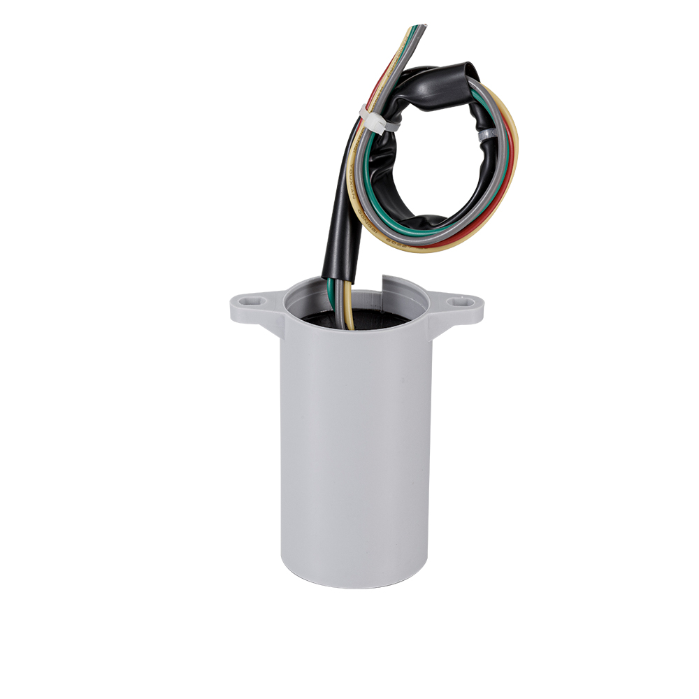
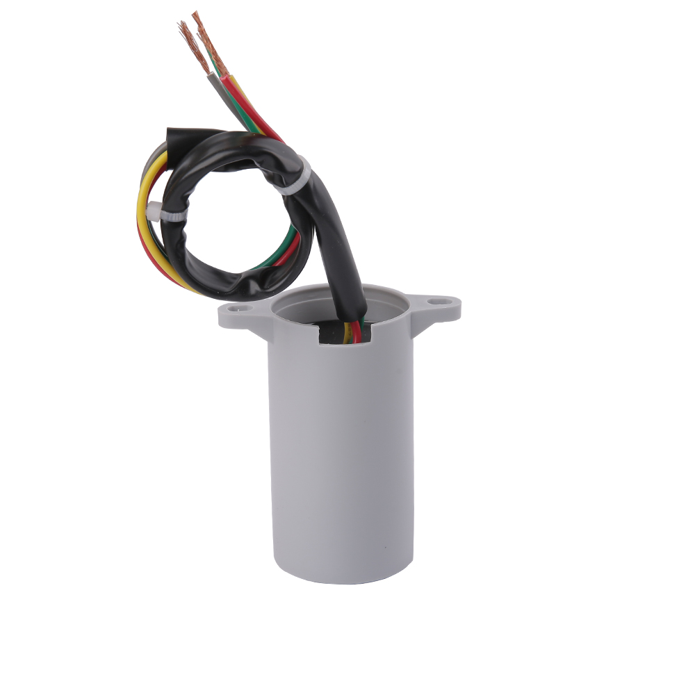
CBB60 capacitors are available in multiple case styles. The most common are round cylindrical (with screw terminals or wire leads) and oval cross-section with wire leads. The case dimensions must allow the replacement to physically fit in the mounting location of the original. Verify the height, diameter (or width for oval units), and lead length/style before ordering.
Step 5: Confirm Temperature Rating
CBB60 capacitors are rated for maximum ambient operating temperature, typically 70°C, 85°C, or 105°C. For motors in enclosed housings, outdoor pumps, or high-temperature environments, selecting a capacitor with a higher temperature rating (85°C or 105°C) extends service life significantly. A capacitor rated only to 70°C installed in an outdoor pump motor in a tropical climate may fail within months despite having the correct µF and voltage ratings.
How Capacitors Lose uF Over Time
Capacitors are not permanent components. Over time, the effective capacitance of a CBB60 capacitor — or any other type — decreases due to several aging mechanisms:
Dielectric Degradation
The polypropylene film in a CBB60 capacitor is an excellent dielectric, but it is not immune to degradation. Prolonged exposure to temperatures above its rating accelerates molecular changes in the polymer structure, reducing the dielectric constant and therefore the capacitance. A CBB60 capacitor operating continuously at 10°C above its rated temperature experiences significantly accelerated aging — a general rule in capacitor engineering is that every 10°C increase in operating temperature roughly doubles the rate of aging, following the Arrhenius relationship used in reliability engineering.
Self-Healing Events
Each self-healing event — where a localized dielectric breakdown causes a small area of metallization to evaporate — slightly reduces the effective electrode area of the capacitor and therefore its capacitance. Under normal operating conditions, these events are rare and the cumulative capacitance loss over years is small. However, capacitors subjected to frequent overvoltage, high-frequency switching transients, or operation in high-temperature environments experience more self-healing events and lose capacitance faster.
Moisture Ingress
Although CBB60 capacitors use sealed plastic cases, prolonged exposure to high-humidity environments can allow moisture to slowly permeate the enclosure. Moisture in contact with the metallized film causes oxidation, increasing the equivalent series resistance (ESR) and reducing capacitance. Outdoor applications — particularly submersible pumps and irrigation systems — should use CBB60 capacitors with enhanced sealing and moisture-resistant outer cases where available.
In service, a CBB60 capacitor that has fallen to 85% or less of its rated µF value should be considered due for replacement, even if the motor is still functioning. Running a motor continuously with a significantly degraded capacitor accelerates winding insulation deterioration and shortens the motor's remaining service life.
CBB60 vs. Other Motor Capacitor Types: A uF Comparison
| Capacitor Type | Typical µF Range | Duty Cycle | Self-Healing | Typical Service Life |
|---|---|---|---|---|
| CBB60 (Metallized PP Film) | 1–100 µF | Continuous (100%) | Yes | 30,000+ hours |
| Motor Start (Electrolytic) | 50–600 µF | Short-term only (1–3 sec) | No | 3,000–10,000 starts |
| CBB65 (AC Compressor) | 15–80 µF | Continuous (100%) | Yes | 30,000+ hours |
| CBB61 (Fan Motor) | 1–20 µF | Continuous (100%) | Yes | 30,000+ hours |
| Oil-Impregnated Paper (Legacy) | 1–60 µF | Continuous | No | 5,000–15,000 hours |
The data above reflects typical specifications from manufacturers' published product catalogs and industry standards. The CBB60 capacitor's combination of continuous-duty rating, self-healing capability, wide µF range, and long service life makes it the overwhelming choice for motor-run applications in modern equipment.
Frequently Asked Questions About uF Capacitor Meaning
What does uF mean on a capacitor?
uF stands for microfarad, a unit of electrical capacitance equal to one-millionth of a farad (10⁻⁶ F). It quantifies how much electrical charge a capacitor can store per unit of voltage. The notation "uF" is identical in meaning to "µF" — the "u" is simply a typographic substitute for the Greek letter mu (µ) when that character is unavailable.
Can I replace a capacitor with a higher uF value?
For motor-run capacitors including CBB60 capacitors, the answer is generally no — not significantly higher. A replacement capacitor should match the original µF rating within ±5% to ±10%. Using a substantially higher uF value increases the auxiliary winding current beyond its rated level, causing overheating and shortened motor life. A slightly higher value (within the ±10% tolerance) is sometimes used when an exact match is unavailable, but going 20% or more above the rated value is not recommended.
Is a CBB60 capacitor the same as a run capacitor?
Yes — the CBB60 is a type of motor-run capacitor. The CBB60 designation specifies the construction standard (metallized polypropylene film, AC-rated) and the application category (motor running). All CBB60 capacitors are motor-run capacitors, but not all motor-run capacitors are CBB60 units — older designs used oil-impregnated paper construction with similar µF ratings but different construction and lifespan.
How do I know what uF capacitor my motor needs?
The most reliable method is to read the label on the existing capacitor or the motor nameplate. The capacitor's µF rating will be printed on the body, usually alongside the voltage rating (e.g., "12µF 450V"). If the original capacitor is missing or unreadable, consult the motor manufacturer's documentation, the equipment service manual, or use the motor's rated power and supply voltage to calculate the theoretical required capacitance — which typically ranges from 6 µF to 10 µF per kilowatt of motor power for single-phase induction motors, though this is an approximation that varies by motor design.
What happens if I use a capacitor with the wrong uF rating?
Using a significantly lower uF value results in insufficient phase shift, reducing starting torque and running efficiency. The motor may fail to start under load, run hotter than normal, and draw more current. Using a significantly higher uF value increases auxiliary winding current beyond the motor's rated limit, causing overheating and insulation degradation. In both cases, the motor's service life is shortened. Matching the uF rating within the specified tolerance is essential for correct and reliable motor operation.
What is the difference between uF, nF, and pF?
These are three units of capacitance that differ by factors of 1,000. One microfarad (1 µF or 1 uF) equals 1,000 nanofarads (1,000 nF) and equals 1,000,000 picofarads (1,000,000 pF). Motor-run capacitors like CBB60 units are measured in µF (typically 1–100 µF). Signal-processing and audio capacitors are often specified in nF (0.001–999 nF). High-frequency RF and precision timing capacitors are specified in pF (1–999 pF). The selection of unit depends entirely on the application; there is no technical difference between 0.1 µF and 100 nF — they are the same capacitance expressed in different units.
How long does a CBB60 capacitor last?
Under ideal conditions — operating within rated temperature and voltage, in a clean and dry environment — a quality CBB60 capacitor is rated for 30,000 hours or more of continuous operation. At 8 hours of use per day, this corresponds to approximately 10 years of service life. In practice, factors such as ambient temperature, voltage surge frequency, humidity, and the number of motor starts all affect actual service life. Capacitors in outdoor pump applications exposed to heat and humidity may need replacement every 3 to 5 years even with quality units. Regular capacitance testing with a multimeter or LCR meter allows capacitor condition to be monitored proactively rather than waiting for failure.
Why is the µ symbol sometimes written as u in capacitor labeling?
The Greek letter µ (mu) is not part of the basic ASCII character set and was not available on many early label-printing machines, keyboard layouts, or marking systems. The Latin letter "u" was adopted as a practical substitute because it has a similar visual appearance (lowercase u resembles µ) and the substitution became so widespread in engineering and manufacturing that it is now universally accepted. Both µF and uF unambiguously mean microfarad in any electrical or electronic context. Modern digital labeling systems are fully capable of printing the actual µ symbol, but the "u" convention persists because of its long history and broad recognition in the industry.
Can a capacitor with the right uF rating but wrong voltage rating be used?
No — the voltage rating must meet or exceed the application requirement. A capacitor rated at 250V AC cannot safely replace a 400V AC unit on a 220V circuit, because mains voltage fluctuations and transient spikes may momentarily exceed 250V, causing dielectric breakdown. The result is either gradual premature capacitance loss or catastrophic failure. Using a higher-voltage-rated replacement (e.g., 450V AC where 400V AC is specified) is acceptable and provides an additional safety margin, but the voltage rating must never be reduced below the original specification.
What is the capacitance tolerance for CBB60 capacitors?
Standard CBB60 capacitors are produced with capacitance tolerances of ±5% (designated J) and ±10% (designated K). The ±5% tolerance is the most common in quality-grade CBB60 capacitors and is the preferred specification for motor-run applications where consistent performance is important. Some budget-grade capacitors may carry ±10% tolerance markings. Both are acceptable, but when replacing a failed CBB60 in a precision application, selecting a ±5% tolerance unit provides the most predictable motor performance.


 +86-13600614158
 +86-0574-63223385
 Zonghan Street,Cixi City,Zhejiang Province,China.