
 en
 English

How to Connect a Motor Capacitor: Start vs Run Wiring Guide with Safety Tips
Content
- 1 Start Capacitors and Run Capacitors: Understanding the Difference
- 2 Which Way to Connect a Capacitor? Polarity Rules Explained
- 3 How to Wire a Two-Terminal Motor Capacitor: Step-by-Step
- 4 Connecting a Three-Terminal Dual-Run Capacitor: HERM, FAN, and C
- 5 How to Connect a Four-Terminal Capacitor
- 6 Common Capacitor Connection Mistakes and How to Avoid Them
- 7 Capacitor Safety: Discharge and Handling Before Wiring
- 8 Frequently Asked Questions About Capacitor Connections
- 8.1 Does it matter which way you connect a motor capacitor?
- 8.2 What happens if you hook up a capacitor backwards?
- 8.3 How do I discharge a capacitor before touching it?
- 8.4 Can I use a larger microfarad run capacitor to get more torque?
- 8.5 Which wire goes to the HERM terminal on a dual-run capacitor?
- 8.6 Why are run capacitors rated 370 V and 450 V when the mains is only 230 V?
Connecting a motor capacitor is more about choosing correctly than about orientation. For the alternating-current film capacitors used in washing machines, water pumps, cooler motors, compressors, and condenser fans, the two terminals are electrically identical, so wire direction does not affect operation. These capacitors are non-polarized: either wire can go to either terminal without changing motor performance, rotation, or capacitor life. The real connection rules concern capacitor type, capacitance value, voltage rating, and circuit position, not the physical direction of the two leads.
Field failures after replacement usually come from a small set of repeatable errors: installing a start capacitor where a run capacitor is required, ignoring the voltage rating, mixing up the terminals of a dual-run capacitor in HVAC equipment, and handling a charged capacitor without discharging it first. This guide gives the conclusion first, then walks through the practical wiring steps, terminal identification, common mistakes, and safety checks in the same order a technician would apply them on the job.
Start Capacitors and Run Capacitors: Understanding the Difference
A capacitor makes a single-phase motor self-starting by shifting the phase of the current in the auxiliary winding. Start capacitors and run capacitors do this in different ways, and they are wired into different positions in the motor circuit.
A start capacitor produces a strong phase shift for a short period. Typical values range from 100 to 300 uF, and the capacitor is switched into the circuit by a centrifugal switch or start relay, then removed once the motor reaches roughly 75% of rated speed. Because it stays energized for only a few seconds, it is not rated for continuous duty. Leaving a start capacitor energized will overheat its internal structure and cause early failure.
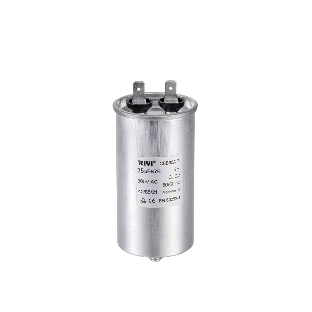
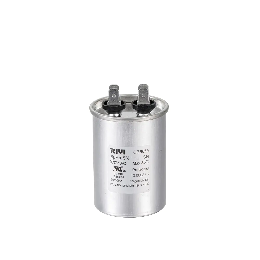
A run capacitor, by contrast, remains in the circuit for the entire running time. Typical values range from 2.5 to 60 uF for appliance and pump motors. It improves running efficiency and power factor. Run capacitors are oil-filled metallized polypropylene film types, commonly rated 370 or 450 V AC for 230 V mains circuits.
| Comparison item | Start capacitor | Run capacitor |
|---|---|---|
| Duty cycle | Intermittent, only during startup | Continuous, full running time |
| Typical capacitance | 100 to 300 uF | 2.5 to 60 uF |
| Common voltage rating | 125 to 330 V AC | 370 to 450 V AC |
| Internal construction | Electrolytic or film, short duty | Oil-filled metallized polypropylene film |
| Circuit position | In series with the start winding and switching device | In series with the start winding, always connected |
Which Way to Connect a Capacitor? Polarity Rules Explained
Conclusion first: if the capacitor is an unmarked, two-terminal AC motor capacitor, orientation does not matter. If it is marked with a plus and minus sign, orientation is critical.
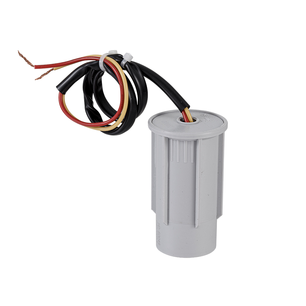
AC motor capacitors are non-polarized. The internal film electrodes are symmetrical, so reversing the two leads changes nothing measurable. The capacitor charges, discharges, and phase-shifts identically in both directions. This is why a round or oval CBB60, CBB61, or CBB65 capacitor can be connected to a washing machine, water pump, or cooler motor with the leads in either order.
Polarized capacitors, usually DC electrolytics, have a clearly marked negative stripe and a positive terminal. In a DC circuit such as a power supply stage, the positive terminal must connect to the higher-potential rail, typically the positive supply, and the negative terminal to the lower-potential side, usually ground. Reversing a polarized capacitor breaks down the internal oxide layer, current rises sharply, and the capacitor heats, vents, bulges, or fails as a short circuit. Electrolyte can spray from the vent in an extreme case.
The practical rule for the workbench: two unmarked terminals on an AC film capacitor means either direction is safe, but the capacitor must still be the correct type, capacitance, and voltage rating for the motor.
How to Wire a Two-Terminal Motor Capacitor: Step-by-Step
These steps cover the large majority of appliance and equipment motors that use a permanent split capacitor (PSC) or capacitor-start design. Follow them in order.
- Switch off the supply at the breaker or disconnecting means and verify zero voltage at the motor terminals with a multimeter.
- Discharge the capacitor by placing a 10 kilohm, 5 watt resistor across the two terminals for about five seconds, then confirm the DC voltage reading is 0 V.
- Identify the motor leads. The start winding lead is usually marked or color-coded; if no marking is present, use the motor wiring diagram on the nameplate.
- For a run capacitor in a PSC motor, connect one capacitor lead to the start winding lead and connect the other capacitor lead to the same line conductor that feeds the main winding.
- For a start capacitor with a centrifugal switch or relay, connect one capacitor lead to the start winding lead and connect the other to the switch output that opens when the motor reaches speed.
- Use a secure termination: push-on tabs made for the capacitor, crimped ring terminals, or wire nuts. Inspect that no copper strands are exposed.
- Check the capacitor value and voltage rating against the motor nameplate before the connection is energized.
- Energize the motor briefly. It should reach speed quickly without excessive hum. If it hums and stays slow, re-check the capacitor value, the winding connection, and the switch.
Swapping the two capacitor leads does not change motor direction. Rotation direction is changed by swapping the main winding leads, which is a separate operation.
Connecting a Three-Terminal Dual-Run Capacitor: HERM, FAN, and C
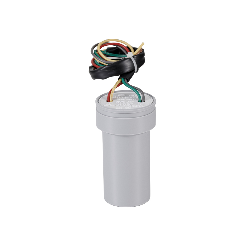
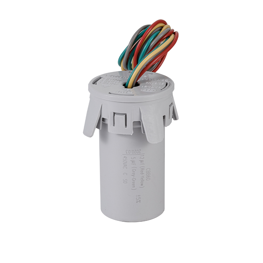
Three-terminal dual-run capacitors are common on air-conditioning condenser units. One case contains two independent capacitor sections. The conclusion up front: the C terminal is the shared common, the larger microfarad section feeds the compressor (HERM), and the smaller microfarad section feeds the condenser fan (FAN).
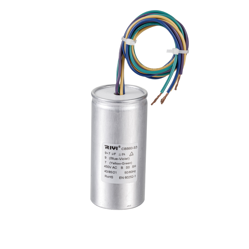
Inside the case, one section sits between C and HERM, and a second section sits between C and FAN. The section ratings are printed on the side label, for example 35 uF plus 5 uF: the 35 uF part is the compressor run capacitor, and the 5 uF part is the fan run capacitor. Label every wire before removing the old capacitor because wire colors vary between manufacturers.
If the label is unreadable, use a multimeter with capacitance mode. Measure the value between C and HERM and between C and FAN. The pair with the higher reading is the compressor section, and the pair with the lower reading is the fan section.
| Terminal | Internal function | Wire destination |
|---|---|---|
| C | Common reference for both sections | Contactor-side common conductor |
| HERM | Compressor run capacitor section | Compressor start winding lead |
| FAN | Condenser fan run capacitor section | Condenser fan motor start winding lead |
How to Connect a Four-Terminal Capacitor
Four-terminal capacitors appear in reversible motors, multi-speed fans, and some appliance designs. The principle is simple: a four-terminal capacitor contains two independent capacitor sections, with terminal A connected internally to terminal B, and terminal C connected internally to terminal D.
The two sections do not share a common terminal, which differs from the three-terminal dual-run capacitor. Each pair is a complete capacitor. Wiring therefore follows two sets of two-terminal rules: connect the A-B pair into one winding circuit and the C-D pair into the other winding circuit.
Follow the printed markings: most four-terminal capacitors show the capacitance value next to each pair. If markings are missing, identify the pairs by measuring capacitance between terminals. Only terminals that belong to the same internal section will produce a reading that matches the expected value on the label. Connecting to the wrong pair will leave one winding circuit open, and the motor will not start.
Common Capacitor Connection Mistakes and How to Avoid Them
In production testing and field returns, the errors in the table below account for nearly all early capacitor failures and motor damage. Verify each point before energizing.
| Mistake | Consequence | Correct practice |
|---|---|---|
| Fitting a start capacitor as a run capacitor | Heating, venting, short service life | Use a film run capacitor rated for continuous duty |
| Fitting a run capacitor as a start capacitor | Weak starting torque, motor may not start under load | Use a start capacitor with sufficient microfarad value |
| Choosing a higher microfarad value than the motor rating | Motor winding overheating | Replace with the exact value printed on the nameplate |
| Choosing a voltage rating below the supply voltage | Internal breakdown and capacitor failure | Select 370 or 450 V AC for 230 V mains circuits |
| Reversing a polarized capacitor | Venting, bulging, short circuit | Check the plus and minus markings before wiring |
| Leaving loose strands at the terminal | Local heating, arcing, connection failure | Use push-on tabs, crimped terminals, or wire nuts |
| Handling a charged capacitor without discharging | Electric shock | Discharge and verify zero volts with a multimeter |
The most damaging mistakes are the ones that look normal at a glance. Identical case shapes make a start capacitor and a run capacitor easy to confuse. Compare the printed microfarad value and the duty rating before installation, not after the motor overheats.
Capacitor Safety: Discharge and Handling Before Wiring
A capacitor stores energy after the power is off. For a 30 uF capacitor charged to the 325 V peak of a 230 V mains line, the stored energy is about 1.6 joules, calculated as 0.5 multiplied by the capacitance in farads multiplied by the voltage squared. That is enough for a painful shock and a dangerous reflex reaction.
The discharge procedure we recommend: place a 10 kilohm, 5 watt resistor across both terminals for five seconds, then confirm a 0 V reading on the multimeter. Film capacitors can regain a small charge from dielectric absorption after the first discharge, so wait about one minute and check the reading again before touching the terminals or wiring the part.
- Use insulated tools and wear safety glasses while removing or installing capacitors.
- Never handle a capacitor that is hot, bulged, or leaking; replace it with the same capacitance and voltage rating.
- Do not short the terminals with a metal screwdriver blade; a resistor discharge is slower and safer.
- For permanently installed capacitors, leave a bleeder resistor connected across the terminals as good practice.
Frequently Asked Questions About Capacitor Connections
Does it matter which way you connect a motor capacitor?
No, not for AC motor capacitors. These are film capacitors with symmetrical electrodes, so the two leads are interchangeable. The motor starts and runs identically in either direction. Only polarized DC electrolytic capacitors require strict polarity.
What happens if you hook up a capacitor backwards?
For an AC motor capacitor, nothing. Both terminals are equivalent, so there is no backwards installation. For a polarized electrolytic capacitor, reverse voltage breaks down the oxide layer, causing heating, venting, bulging, and eventually a short circuit. Do not test a polarized capacitor with reversed leads, even briefly.
How do I discharge a capacitor before touching it?
Connect a 10 kilohm, 5 watt resistor across both terminals for about five seconds, confirm 0 V on a multimeter, wait 60 seconds, and check again. Never rely on a screwdriver short; the discharge current is uncontrolled and can damage the terminals or startle you badly enough to cause an accident.
Can I use a larger microfarad run capacitor to get more torque?
No. The run capacitor value is matched to the motor winding. A larger value increases winding current and operating temperature, which shortens motor life. If the motor struggles to start, check the start capacitor, the supply voltage, and the mechanical load instead of increasing the microfarad rating.
Which wire goes to the HERM terminal on a dual-run capacitor?
The compressor start winding lead goes to HERM, the condenser fan motor start winding lead goes to FAN, and the common conductor from the contactor goes to C. When labels are missing, measure capacitance between the terminal pairs: the higher value is the compressor section.
Why are run capacitors rated 370 V and 450 V when the mains is only 230 V?
Motor circuits produce voltage spikes when the switch opens and when the load changes. The extra margin above the 230 V supply prevents internal breakdown and extends capacitor life. Always select a capacitor with a voltage rating at least equal to the motor supply voltage, and preferably 450 V AC for long service on 230 V mains.


- Tel: +86-13600614158
- E-mail: mina@cxriyi.com
- Address: Zonghan Street,Cixi City, Zhejiang Province, China.
Copyright © CIXI RIYI CAPACITOR FACTORY
All Rights Reserved.
 custom air conditioner capacitor for sale
China Ac Motor Capacitor Factory