
 en
en
 English
How to Test a Ceiling Fan Capacitor: A Practical Multimeter Testing Guide
Content
- 1 How to Test a Ceiling Fan Capacitor in Six Steps
- 2 Before You Start: Safety Rules and the Tools You Need
- 3 Step One: Visual Inspection, the Fastest Diagnosis
- 4 Step Two: Capacitance Test with a Digital Multimeter
- 5 Step Three: Resistance Test When Your Meter Has No Capacitance Mode
- 6 Multimeter Readings at a Glance
- 7 Testing 3-Wire, 4-Wire, and 5-Wire Ceiling Fan Capacitors
- 8 When the Capacitor Tests Good: Other Causes of Ceiling Fan Problems
- 9 Choosing the Right Replacement CBB61 Ceiling Fan Capacitor
- 10 Frequently Asked Questions About Ceiling Fan Capacitor Testing
- 10.1 Can I test a ceiling fan capacitor without a multimeter?
- 10.2 What should a ceiling fan capacitor read on a multimeter?
- 10.3 Can I use a capacitor with a higher microfarad rating?
- 10.4 Can I use a capacitor with a higher voltage rating?
- 10.5 Why does my ceiling fan work on high speed but not low?
- 10.6 How long should a ceiling fan capacitor last?
The short answer: disconnect the fan from the power supply at the breaker, discharge the capacitor, set your digital multimeter to capacitance mode, and compare the reading with the value printed on the capacitor case. A reading that is more than 5% below the printed value means the capacitor is weak; a reading that is more than 10% below, or reads zero or OL, means the capacitor has failed and needs replacement.
A ceiling fan capacitor is a small film capacitor, almost always the rectangular CBB61 type, that shifts the phase of the current in the auxiliary motor winding. That phase shift creates the rotating magnetic field that starts the blades turning and keeps them moving at the selected speed. Because the capacitor sits close to the motor and absorbs voltage spikes every time the fan starts, it is the single most frequently replaced component in a ceiling fan.
Test the capacitor whenever the fan hums but will not spin, runs slower than it used to, starts only when the blades are pushed by hand, or drops one or more speed settings. In most ceiling fan service calls, the capacitor turns out to be the failed part, so it is the logical first check before you spend money on a motor or a switch.
How to Test a Ceiling Fan Capacitor in Six Steps
- Turn off the ceiling fan circuit at the breaker panel, not just at the wall switch, and verify zero voltage with a non-contact tester.
- Discharge the capacitor by briefly shorting both terminals with an insulated screwdriver held by the handle.
- Open the fan canopy, photograph the wiring with your phone, then remove the capacitor wires with needle-nose pliers.
- Set the multimeter to capacitance mode and touch the probes to the two capacitor terminals.
- Wait two to three seconds for the reading to stabilize and write the number down.
- Compare the reading with the rating printed on the capacitor; if it is off by more than 10%, replace the capacitor.
The sections below cover the capacitance test in detail, the resistance test you can use as a backup, how to interpret every possible reading, how to test 3-wire and 4-wire multi-speed capacitors, and what to check next when the capacitor measures fine.
Before You Start: Safety Rules and the Tools You Need
Testing a capacitor is safe only when you follow a fixed order: disconnect first, verify zero voltage, then discharge the capacitor. The wall switch is not enough of a safety point because the wiring inside the canopy can still be live from another part of the branch circuit, and a capacitor can hold a residual charge for minutes after the fan stops.
Disconnect and verify
Switch off the ceiling fan circuit at the breaker panel and put a note on the panel if other people are in the house. After removing the canopy, hold a non-contact voltage tester near each wire to confirm that no power is present. Touch nothing until the tester stays silent.
Discharge the capacitor
Take an insulated screwdriver by the handle only, place the metal blade across both capacitor terminals at the same time, and hold it there for two seconds. Repeat the process once. You may hear a small click or see a tiny spark, which is normal. Then set the multimeter to DC volts and confirm the capacitor reads zero before you handle the wires.
Tools you will need
| Tool | Where you use it | Why it matters |
|---|---|---|
| Digital multimeter with capacitance mode | At the capacitor terminals | Measures the microfarad value, the only reliable pass or fail test |
| Non-contact voltage tester | On the supply wires inside the canopy | Confirms zero live voltage before you touch anything |
| Insulated screwdriver | Across the capacitor terminals | Discharges residual charge safely |
| Needle-nose pliers | Removing push-on connectors | Extracts the terminals without bending or tearing the wires |
| Smartphone camera | Before disconnecting anything | Records wire colors and positions for an easy reinstall |
| Safety gloves and glasses | Throughout the test | Protect against sharp metal edges and a rare capacitor vent |
Step One: Visual Inspection, the Fastest Diagnosis
Before you disconnect a single wire, examine the capacitor in place. A large share of failed ceiling fan capacitors fail visibly, and a visible failure needs no multimeter. Look through the housing openings and check the plastic case from every angle.
- A bulged or domed top surface, which indicates internal film breakdown and gas buildup.
- Cracks or chipped edges on the plastic housing, often where the mounting clips press hardest.
- Melted or darkened plastic around the terminals, typical after loose connections heat up.
- Oily or waxy residue leaking from the seams of the case.
- Scorched, discolored, or corroded terminal connections.
- A burnt smell coming from the switch housing area even before you open it.
If any of these conditions are present, skip the electrical test and go straight to replacement. The capacitor has lost its internal film integrity, and no measurement will make it usable again. For a more complete picture of early failure behavior, read our guide to the warning signs of a failing AC capacitor.
Step Two: Capacitance Test with a Digital Multimeter
Why the microfarad value decides everything
The value printed on the capacitor, for example 3 µF, is the nominal capacitance. The motor torque curve and the winding currents are designed around that number. When the metalized film degrades, the capacitance drops, the phase shift changes, and the motor loses torque and speed. That is why the capacitance reading is the single most useful measurement available.
Running the test
- Discharge the capacitor as described in the safety section.
- Remove the fan canopy by loosening the screws on the downrod bracket and lowering the cover.
- Photograph the wire connections with your phone so you can reverse the process later.
- Pull the push-on terminals off with needle-nose pliers, gripping the terminal rather than the wire.
- Set the multimeter to capacitance mode, usually marked with the symbol µF on the dial.
- If the meter has a manual range selector, choose a range above the printed value of the capacitor.
- Place the probes on the two terminals; a ceiling fan capacitor is non-polarized, so probe polarity does not matter.
- Hold the probes steady and wait two to three seconds for the display to settle.
- Write down the reading and compare it with the label on the case.
How to read the result
A healthy film capacitor reads within ±5% of the printed value. For a 3 µF capacitor, the acceptable window is roughly 2.85 to 3.15 µF. Film capacitors age, so a reading of 2.7 µF is marginal and the fan may already have lost speed. Below 2.7 µF, the capacitor is too weak to supply the phase shift the motor needs and should be replaced.
The rule used by most technicians is simple: replace the capacitor if the measured value is more than 10% below the printed rating, regardless of whether the fan still runs. If you want to understand how far a capacitor can drift before performance suffers, read our explanation of how capacitance deviation affects fan performance.
Step Three: Resistance Test When Your Meter Has No Capacitance Mode
A basic multimeter without a capacitance mode can still catch the two most common failure modes: an open capacitor and a shorted capacitor. This test cannot measure the exact microfarad value, so it is a backup, not a replacement for the capacitance test.
How the resistance test works
When you connect the probes, the meter injects a small current from its internal battery into the capacitor. A healthy capacitor accepts that charge, so the resistance appears low at the moment of connection and climbs as the charge builds, eventually reaching a very high value near the top of the scale.
Procedure
- Set the multimeter to the highest ohms range, typically 200 kΩ or 20 MΩ.
- Connect the probes to the two capacitor terminals.
- Watch the display for five to ten seconds and note whether the value moves.
What the movement tells you
A reading that climbs steadily and settles near the top of the range means the capacitor charges normally and is neither open nor shorted. A reading that stays pinned at zero means the plates are shorted together. A reading that never moves from the top of the range means the internal connection to the film is broken. Both the permanently zero reading and the permanently high reading are definite failure signals.
An analog multimeter makes this test even easier to read: the needle should swing up for a moment, then ease back toward infinity on a good capacitor. If the needle does not move at all, the capacitor is open; if it stays at zero, the capacitor is shorted.
Multimeter Readings at a Glance
The table below summarizes every common result from both test methods. Keep it beside your multimeter during the first few checks until the interpretation becomes automatic.
| Test type | Reading you see | Diagnosis | Action |
|---|---|---|---|
| Capacitance | Within ±5% of printed value | Healthy | Check the switch and motor next |
| Capacitance | 5% to 10% below printed value | Marginal | Monitor; replace if the fan still runs weak |
| Capacitance | More than 10% below printed value | Worn capacitor | Replace the capacitor |
| Capacitance | Zero or near zero | Shorted internally | Replace the capacitor |
| Capacitance | OL on the display | Open circuit | Replace the capacitor |
| Resistance | Climbs and settles near the top | Capacitor charges normally | Good; check other parts |
| Resistance | Stays at zero | Shorted | Replace the capacitor |
| Resistance | Does not move from the top | Open circuit | Replace the capacitor |
If your capacitor falls into one of the healthy rows but the fan still behaves badly, the fault lies elsewhere in the fan. The section after the next one walks through the other usual suspects.
Testing 3-Wire, 4-Wire, and 5-Wire Ceiling Fan Capacitors
A fixed-speed fan uses a simple two-wire capacitor. Multi-speed fans use a capacitor with three, four, or five wires because each speed setting energizes a different capacitance section, which produces a different phase shift and therefore a different motor speed.
Understanding a 3-wire CBB61 capacitor
A 3-wire capacitor is two capacitors inside one housing with a shared common terminal. A label reading 3 µF + 3.5 µF means that section one is 3 µF, section two is 3.5 µF, and one of the three wires is electrically common to both sections. The common wire is usually a different color from the two speed wires; the diagram printed on the case identifies which is which.
Testing each section of a multi-wire capacitor
- Find the wiring diagram printed on the capacitor case and identify the common terminal.
- Test between the common terminal and each of the other terminals one at a time.
- Compare each reading with the value printed next to each wire color.
- If any single section is open, shorted, or more than 10% below its rating, replace the whole capacitor even if the other sections test fine.
- Do not treat a reading between the two speed wires as a separate section; that reading is the series combination of the two internal capacitors and carries no diagnostic meaning for a 3-wire part.
| Wire pair tested | Printed value | Measured example | Result |
|---|---|---|---|
| Common (black) to gray | 3.5 µF | 3.42 µF | Good section |
| Common (black) to purple | 3 µF | 2.15 µF | Weak section, replace whole capacitor |
| Gray to purple | No printed value | Around 1.6 µF | Series combination, ignore |
The same logic applies to 4-wire and 5-wire types, which simply contain three or four sections sharing one common lead. Test every section because a capacitor usually fails in one winding section first, leaving you with a fan that works on only some speeds. If you need a direct replacement in a modern fan, insert-terminal CBB61 fan capacitors are the most common push-on style used today.
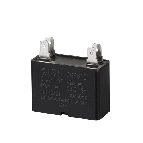 Wholesale Cbb61 Insert Type Square Motor Capacitor SuppliersAs advanced Cbb61 Square Motor Capacitor Suppliers in China, Cixi Riyi Capacitor Factory wholesale Cbb61 Insert Type Square Motor Capacit...View Product →
When the Capacitor Tests Good: Other Causes of Ceiling Fan Problems
A capacitor that reads within tolerance is not automatically the end of the investigation. If the capacitance test says the part is healthy and the fan still refuses to start, runs slow, or loses speeds, check these areas before ordering any parts.
- Pull-chain switch. The most common false suspect. Worn contacts inside the switch produce missing speeds, intermittent operation, and a fan that starts only after several pulls. Test it with the multimeter in continuity mode.
- Remote or wall-control receiver. A failed relay or a cold solder joint in the receiver can stop one speed or all speeds while the capacitor remains fine.
- Motor windings. Measure the main and auxiliary windings with the ohms range; both should read low and relatively close to each other. A reading near infinity means the winding is open and the motor, not the capacitor, is the problem.
- Loose or corroded connections. Push-on terminals loosen over years of thermal cycling, and a loose connection can starve the capacitor of voltage even when the capacitor itself is healthy.
- Bearing and lubrication. A dry or gummed bearing makes the fan hum and struggle to spin, closely mimicking a weak capacitor. Spin the blades by hand with the power off; they should rotate smoothly and coast for several revolutions.
A fan that works on high speed but not low is routinely blamed on a failed capacitor section when the real culprit is the switch. That is exactly why testing, not guessing, saves you a wasted replacement part.
Choosing the Right Replacement CBB61 Ceiling Fan Capacitor
Once the test says replace, choose the new capacitor by matching four electrical ratings and one mechanical detail: capacitance, voltage, temperature class, wire count, and mounting layout. For ceiling fans, the correct family is always CBB61. The typical CBB61 ceiling fan capacitor range covers 1.5 µF to 6 µF in 250 V, 400 V, and 450 V versions, with either 85°C or 105°C temperature classes.
China Cbb61 Square Motor Fan Capacitor Manufacturers, FactoryAs leading China cbb61 capacitor manufacturers and Fan Capacitor suppliers, Cixi Riyi Capacitor Factory produce Cbb61 Square Motor Fan Ca...View Product →
| Specification | Match guideline | Why it matters |
|---|---|---|
| Capacitance (µF) | Identical to the printed value | A higher value raises current and overheats the motor; a lower value reduces torque |
| Voltage rating (V) | Equal or higher than the original | A 450 V part safely replaces a 250 V part and handles mains surges better |
| Temperature class | 85°C or 105°C | A 105°C rated film degrades slower inside the confined canopy heat |
| Wire configuration | Same number of wires and same layout | Plug-and-play installation with the existing switch leads |
| Mounting and dimensions | Fits the original bracket and housing | Avoids drilling or cutting the fan housing |
A voltage rating higher than the original is always acceptable; a 450 V capacitor can replace a 250 V one as long as the physical size fits inside the housing. A capacitance rating higher than the original is never acceptable; it increases the current in the auxiliary winding and can burn the motor over time. Keep the replacement within ±5% of the original microfarad value, and never exceed 10% in either direction.
Before ordering, confirm the wire configuration of your fan. Pull-chain designs with soldered speed wires need flying leads, while push-on quick-connect fans need insert terminals. For solder-style installations, lead-wire CBB61 fan capacitors are the correct pick. Once the new part arrives, reverse the removal process using the photos you took; the complete motor run capacitor replacement procedure walks through every step from removal to the final spin test.
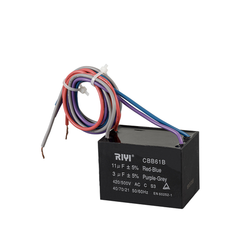 Wholesale Cbb61 Square Motor Capacitor With Wire Lead SuppliersAs advanced Cbb61 Square Motor Capacitor Suppliers in China, Cixi Riyi Capacitor Factory wholesale Cbb61 Square Motor Capacitor With Wire...View Product →
Frequently Asked Questions About Ceiling Fan Capacitor Testing
Can I test a ceiling fan capacitor without a multimeter?
A careful visual inspection catches a bulged, melted, cracked, or leaking capacitor, and a manual spin test can provide a rough clue: with the power off, spin the blades by hand, then switch the fan on at high speed. If the fan runs after a push, the capacitor may be weak but is not completely open. These checks cannot confirm the microfarad value, so a multimeter remains the only accurate method.
What should a ceiling fan capacitor read on a multimeter?
It should read within about ±5% of the microfarad value printed on the case. For a fan marked 3 µF, a healthy reading is roughly 2.85 to 3.15 µF. If it reads below 2.7 µF and the fan is sluggish, the capacitor has degraded and should be replaced.
Can I use a capacitor with a higher microfarad rating?
No. A higher microfarad value increases the current through the auxiliary motor winding, which makes the motor run hotter and can burn it out. Always match the original microfarad value; the tolerance of the replacement should be within ±5%, and 10% is the absolute ceiling.
Can I use a capacitor with a higher voltage rating?
Yes. The voltage rating is a maximum limit, not a required operating voltage. A 450 V capacitor works safely on a 220-240 V fan and even on a 120 V fan, as long as the physical dimensions fit inside the canopy. The only ratings that must stay identical are capacitance, wire count, and wiring configuration.
Why does my ceiling fan work on high speed but not low?
Multi-speed fans switch different capacitor sections for different speeds. A worn lower-speed section will make the fan fail on that speed while the high-speed section still tests fine. Use the capacitance test on every section of a 3-wire or 4-wire capacitor; if the section for low speed reads low or open, replace the entire capacitor rather than trying to repair it.
How long should a ceiling fan capacitor last?
Most run capacitors show measurable degradation after five to ten years of regular operation, depending on heat exposure, voltage spikes, and how many hours the fan runs. A quality CBB61 with a 105°C temperature class mounted in a well-ventilated canopy tends to hold its capacitance longer. Heat is the leading cause of early failure, so keeping the fan clean and the canopy vents clear extends capacitor life.


- Tel: +86-13600614158
- E-mail: mina@cxriyi.com
- Address: Zonghan Street,Cixi City, Zhejiang Province, China.
Copyright © CIXI RIYI CAPACITOR FACTORY
All Rights Reserved.
 custom air conditioner capacitor for sale
China Ac Motor Capacitor Factory
custom air conditioner capacitor for sale
China Ac Motor Capacitor Factory