
 en
en
 English
How to Wire a Capacitor to an Electric Motor: Complete Start & Run Guide
Wiring a capacitor to an electric motor looks simple until the motor hums without turning, the overload trips, or the capacitor case swells into a bulge. Every one of those failures traces back to the same root cause: one wire landed on the wrong terminal, or the wrong capacitor type was used for the job. The practical difference between a successful repair and a burned-out winding is often just a few centimeters of wire placement.
Here is the direct answer before we go deeper: a run capacitor connects between the live supply line and the start winding terminal, and it stays in the circuit the entire time the motor runs. A start capacitor connects to the same start winding terminal, but through a relay or a centrifugal switch that takes it out of the circuit after the motor reaches about 75% of full speed. In both cases, the neutral wire goes to the common terminal, not to the capacitor. If you are replacing a failed part, photograph the original wiring first, verify the microfarad and voltage ratings, then reproduce the exact same connections on the new capacitor.
This guide walks through run capacitor wiring, start capacitor wiring, terminal identification, the most common mistakes, and the selection criteria that prevent repeat failures.
Run Capacitor vs Start Capacitor: Two Different Wiring Jobs
Most single-phase motors use a capacitor to create a phase shift between the main winding and the auxiliary winding. That phase shift produces the rotating magnetic field that starts the motor and keeps it turning. But a capacitor that stays in the circuit and a capacitor that only lives in the circuit for two seconds are built differently, rated differently, and wired differently.
What a run capacitor does
A run capacitor remains permanently in series with the auxiliary winding. It improves torque during normal operation, raises the power factor, and reduces current draw. Run capacitors are typically metalized polypropylene film units with capacitance values from 1.5µF to 100µF depending on the motor size. They are rated for continuous AC duty, and the voltage rating is usually 370V or 450V for motors running on 230V supplies. A run capacitor failure usually does not stop the motor instantly, but the motor runs hotter, vibrates more, and loses efficiency.
What a start capacitor does
A start capacitor delivers a strong torque boost during the first second or two of operation. Capacitance values are much higher, typically 70µF to 800µF, and the component is designed for intermittent duty only. If a start capacitor stays in the circuit because the relay is stuck or the centrifugal switch fails, the winding overheats quickly and the capacitor may vent or bulge. Start capacitors are usually connected in series with a normally closed relay contact or a centrifugal switch that opens once the motor reaches speed.
For a quick refresher on the function of each component, check the difference between a start capacitor and a run capacitor in practical terms.
| Feature | Run Capacitor | Start Capacitor |
|---|---|---|
| Position in motor circuit | Permanently in series with auxiliary winding | In series with a relay or centrifugal switch |
| Typical capacitance range | 1.5µF – 100µF | 70µF – 800µF |
| Duty rating | Continuous | Intermittent, seconds per cycle |
| Common case styles | CBB60 cylindrical, CBB61 square | Round aluminum or plastic can |
| Typical failure symptom | Motor runs hot, weak torque, higher current | Motor hums or buzzes, will not start spinning |
Step-by-Step: Wiring a Run Capacitor to a Single-Phase Motor
Follow this sequence in order. Skipping the discharge step is the fastest way to learn what a capacitor feels like when it still holds a charge.
- Disconnect and lock out the power. Open the breaker or remove the fuse, and confirm with a multimeter that the motor terminals read 0V. A capacitor can hold a lethal charge for minutes after the motor is unplugged.
- Discharge the capacitor. Place a 20kΩ, 5W resistor across the two capacitor terminals for at least 10 seconds. Do not short the terminals with a screwdriver; that can damage internal connections and is more dangerous to you.
- Photograph the original wiring before touching anything. Motor wire colors vary between manufacturers, so the photo becomes your reference diagram.
- Verify the replacement ratings. The microfarad value should match the original within ±5%, and the voltage rating should be equal to or higher than the original. For a 230V motor, that usually means a 370V or 450V capacitor.
- Identify the start winding terminal (S). In a typical four-wire motor, one capacitor lead connects to the start winding terminal, which may be marked "S", "Aux", or a specific color such as yellow or white. Use the nameplate diagram whenever it is present.
- Connect one capacitor lead to the live line side. Depending on your motor's internal arrangement, the line may connect directly to the motor's "R" (run) terminal, and the capacitor bridges between the line and the "S" terminal.
- Connect the second capacitor lead to the start winding terminal. This is the lead that supplies the phase-shifted current to the auxiliary winding. The neutral wire connects to the common terminal "C", not to the capacitor.
- Secure all connections and test briefly. Make sure no bare wire touches the capacitor case or the motor frame, then re-energize and run the motor for a few seconds to confirm it starts smoothly and spins in the correct direction.
If the motor runs in reverse, swap the two main winding leads, not the capacitor leads. Reversing the start winding leads can also change direction, but which pair to swap depends on the motor's internal scheme, so always check the nameplate diagram. For a different motor layout, the motor run capacitor replacement procedure shows a practical approach used by service technicians.
Step-by-Step: Wiring a Start Capacitor With a Relay or Switch
A start capacitor is never connected straight across the line without a disconnecting device. On capacitor-start motors, the capacitor sits in series with the start winding, and a centrifugal switch or potential relay removes it once the motor accelerates. Wiring a start capacitor therefore means wiring three components together: the capacitor, the switching device, and the start winding.
Centrifugal switch wiring
In most small motors with an internal switch, the switch terminals are normally closed at rest. The line comes into the common terminal, and the start capacitor is connected between the switch and the start winding. When the rotor reaches speed, the switch opens, and the start capacitor is isolated from the circuit. The run capacitor, if present, remains connected to the start winding through a separate path.
Relay-based wiring
Older and larger motors often use a current or voltage relay mounted near the capacitor. The relay coil senses the start winding current; when the current drops after startup, the relay contact opens and disconnects the start capacitor. In these systems, the capacitor connects between the relay contact and the start winding terminal, and the relay coil is wired in series with the winding itself.
The critical rule: never bypass the relay or switch to force the motor to start. A start capacitor that remains energized will heat rapidly, and within minutes the motor may smoke. If the motor hums and the start capacitor tests fine, suspect the relay or switch first, not the capacitor.
- Line (L) connects to the motor common terminal and to the relay/switch input.
- One start capacitor lead connects to the relay/switch output.
- The other start capacitor lead connects to the start winding terminal (S).
- The run capacitor, if used, connects directly between line and start winding.
How to Identify Motor Terminals: C, S, and R
When the nameplate is unreadable or the wires have lost their colors, you can still identify the terminals with a multimeter. The three terminals on most terminal blocks are marked C (common), S (start), and R (run). The resistance values between them follow a consistent pattern, because the main winding and the start winding have different wire gauges and lengths.
| Measurement | Expected Resistance | What It Indicates |
|---|---|---|
| Between C and R | Lowest reading | Main winding only |
| Between C and S | Medium reading | Start winding only |
| Between S and R | Highest reading | Both windings in series |
To use this method, set the multimeter to ohms, place one probe on a single terminal, and probe the other two terminals. Note both readings, then move the first probe to the next terminal. When you find the pair with the highest resistance, the remaining terminal is the common, C. The main winding sits on the side with the lower of the two readings, which identifies R, and the start winding terminal is the last one, S. Once you know the terminals, the wiring logic becomes simple: line to R, neutral to C, capacitor from line to S.
Understanding the internal construction matters when you are diagnosing a repeated failure. The way AC motor capacitors are built and connected internally explains why certain failures like a swollen case or a melted terminal appear more often on one side of the circuit than the other.
Wiring Mistakes That Damage Motors and Capacitors
Most wiring errors fall into one of five categories, and each leaves a recognizable signature. Knowing these signatures helps you avoid the mistake and also helps you diagnose a motor that was wired incorrectly before you arrived.
- Using a capacitor with a lower voltage rating than the original. A 230V motor running through a 250V capacitor may operate normally at first, but mains voltage spikes can exceed 300V, causing internal breakdown, swelling, and leakage. The safe rule is to use the same voltage rating as the original or one step higher, typically 370V or 450V.
- Oversizing the capacitance in an attempt to get more torque. A run capacitor value that is too high increases current through the auxiliary winding, raises temperature, and shortens both the capacitor and the motor life. Capacitance matching should stay within ±5% of the nameplate value.
- Leaving a start capacitor in the circuit. This happens when a relay is bypassed or a centrifugal switch is stuck. The winding receives excessive phase-shifted current and quickly overheats. If the motor starts and then begins to smoke after a few minutes, inspect the start circuit disconnection components.
- Reversing the start winding connections. A motor that runs backwards after reconnection usually has the start winding polarity reversed. Swapping the two start winding leads corrects the direction, but you must confirm which pair is the start winding first, otherwise you can energize the motor into a short circuit.
- Using a DC-rated capacitor in an AC motor circuit. DC electrolytic capacitors are not designed for continuous AC ripple and will overheat, vent, or rupture. Motor capacitors must be marked for AC motor duty.
In compressors, pumps, and other high-vibration applications, the mechanical environment adds another layer of risk. A capacitor with a weak case can crack internally or at the terminal seal. For these conditions, a CBB65 explosion-proof capacitor provides a reinforced aluminum case and a safer failure mode, which matters when the capacitor is mounted inside a sealed service panel.
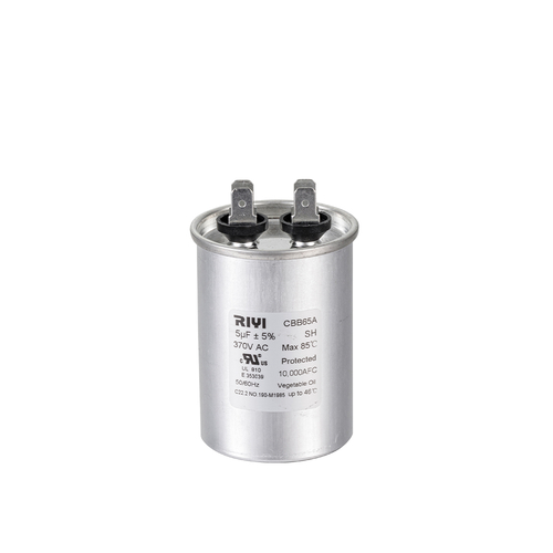 China Cbb65 Explosion-proof Capacitor Manufacturers, FactoryAs leading China cbb65 capacitor manufacturers and Explosion Proof Capacitor suppliers, Cixi Riyi Capacitor Factory produce Cbb65 Explosi...View Product →
How to Select the Right Capacitor Before You Wire It
Correct wiring starts with correct selection. A capacitor with the right ratings but the wrong physical form may not fit the mounting bracket or may place the terminals too close to a live component. Four parameters decide whether a capacitor is suitable for your motor.
Capacitance and voltage
The microfarad rating controls the phase shift angle. A ±5% tolerance is normal for motor run capacitors; going outside that range changes torque and current. The voltage rating must be at least 1.5 times the RMS line voltage. For a 230V motor, that means a 370V rating is the practical minimum, and 450V is common.
Case shape and mounting style
Cylindrical capacitors are the most common motor run capacitors and suit a wide range of mounting clamps. Square capacitors fit tighter spaces and are common in appliance motors. The terminal type matters just as much: push-on tab terminals, screw terminals, and wire leads each require a different connection method, and switching between them usually means replacing the connector, not just the capacitor.
Temperature rating
Motor capacitors are typically rated at 70°C, 85°C, or 105°C. In an enclosed motor housing or a hot pump room, the ambient temperature can exceed 70°C quickly. Installing a 70°C capacitor in a 90°C environment shortens its life dramatically. Match or exceed the temperature class of the original part.
For general pump, fan, compressor, and workshop motor replacements, start with the CBB60 AC motor capacitor range to find a cylindrical can with the right capacitance, voltage, and terminal combination. If your motor compartment is flat and shallow, the CBB61 square motor capacitor series is often easier to fit because the mounting holes align better with the original bracket.
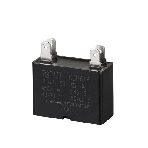 China Cbb61 Square Motor Fan Capacitor Manufacturers, FactoryAs leading China cbb61 capacitor manufacturers and Fan Capacitor suppliers, Cixi Riyi Capacitor Factory produce Cbb61 Square Motor Fan Ca...View Product →
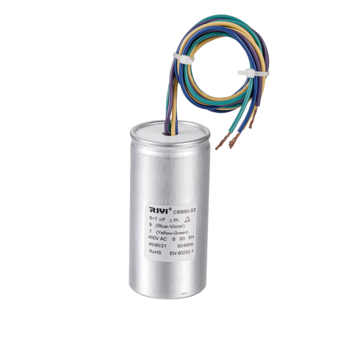 CBB60 AC Motor Run And Start Capacitor Manufacturers, SuppliersAs leading CBB60 capacitor manufacturers and China run & start capacitor suppliers, Cixi Riyi Capacitor Factory wholesale AC motor run ca...View Product →
Frequently Asked Questions About Motor Capacitor Wiring
1. Can I use a capacitor with a higher microfarad rating than the original?
No. A higher microfarad rating increases current in the auxiliary winding, which raises temperature and can shorten motor life. On a run capacitor, the value should stay within ±5% of the nameplate rating. On a start capacitor, the tolerance is somewhat wider, but the correct value is still the one listed on the motor nameplate or in the service manual.
2. Which wire connects to which capacitor terminal?
Motor run capacitors are non-polarized, so it does not matter which wire goes to which terminal for the capacitor itself. What matters is where those two wires lead: one goes to the live line, and the other goes to the start winding terminal. The neutral connects to the motor common terminal, not to the capacitor.
3. Why does the motor hum but refuse to start?
A humming motor with no rotation usually means the start capacitor is not delivering the phase shift, the centrifugal switch is stuck open, or the start winding itself is open. Test the capacitor with a capacitance meter first; if it reads near zero or far above its rated value, replace it. If the capacitor is fine, check the switch and the winding continuity.
4. Do I always need to discharge the capacitor before wiring?
Yes, always. An AC motor capacitor can hold a residual charge even after the supply is disconnected, especially in circuits with rectifiers or when the motor stopped at an unlucky point in the sine wave. Short the terminals through a 20kΩ resistor for 10 seconds, then verify with a voltmeter.
5. Can a run capacitor replace a start capacitor or vice versa?
No, because they are designed for completely different duty cycles. A run capacitor is built for continuous AC current and has a low capacitance; using it as a start capacitor will not deliver enough torque. A start capacitor has a high capacitance and a short intermittent duty rating; using it as a run capacitor will cause it to overheat, swell, and fail within minutes.
6. Why are there two capacitors on some single-phase motors?
These are capacitor-start, capacitor-run motors. The high-value start capacitor provides torque during acceleration and is disconnected by a switch or relay. The lower-value run capacitor stays in the circuit to improve running efficiency and power factor. Each has a separate wiring path, so never replace both with a single capacitor of intermediate value.