
 简体中文
简体中文 English
 Español
 عربى
عربىContent
- 1 The Short Answer: Test Each Half Separately
- 2 What a Dual Run Capacitor Actually Does
- 3 Symptoms That Point to a Bad Dual Run Capacitor
- 4 Safety First: Discharging Before You Test
- 5 Tools You Need for the Test
- 6 Step-by-Step Capacitance Test Procedure
- 7 Interpreting the Readings
- 8 Alternative Tests When You Do Not Have a Capacitance Meter
- 9 Common Mistakes People Make When Testing
- 10 Choosing the Right Replacement After a Failed Test
- 11 Frequently Asked Questions
- 11.1 Can I test a dual run capacitor while it is still connected in the circuit?
- 11.2 What does 35/5 µF mean on a dual run capacitor?
- 11.3 What is the acceptable tolerance for a motor run capacitor?
- 11.4 My multimeter has no capacitance mode. Is there another way to test?
- 11.5 How long does a dual run capacitor normally last?
- 11.6 Should I replace the capacitor if it measures within tolerance but the fan still does not start?
- 12 Final Recommendation
The Short Answer: Test Each Half Separately
A dual run capacitor is essentially two run capacitors inside one aluminum can: the larger section serves the compressor, and the smaller section serves the condenser fan motor. To test it, set a digital multimeter to capacitance mode (µF), put one probe on the C (common) terminal, and take two separate readings — C to HERM for the compressor side, and C to FAN for the fan side. Compare each reading with the two capacitance values printed on the label. If either reading deviates by more than 10% from the printed value, or if the display shows 0 µF or OL, the capacitor is no longer doing its job and should be replaced.
Here is the complete procedure in condensed form:
- Switch off the breaker supplying the condenser unit and verify power is dead.
- Discharge the capacitor through a 20 kΩ resistor or with an insulated screwdriver.
- Photograph the wiring, then disconnect the wires from the C, HERM, and FAN terminals.
- Set the multimeter to capacitance mode.
- Measure C to HERM and write the value down.
- Measure C to FAN and write the value down.
- Compare both readings to the printed µF ratings and decide whether the part passes.
What a Dual Run Capacitor Actually Does
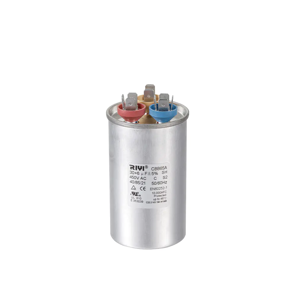
Single-phase AC motors cannot start or run efficiently by themselves because the single feed creates a pulsating magnetic field rather than a rotating one. A capacitor stores energy and releases it with a time delay, producing the phase shift the motor needs to develop torque. In a central air conditioner, both the compressor and the condenser fan motor need that phase shift. Instead of installing two separate cans, most manufacturers combine them into one round or oval aluminum housing with three terminals on top.
The label on the side of the can explains everything. A marking such as 40/5 MFD means the compressor side is 40 µF and the fan side is 5 µF. Voltage ratings are equally important: residential condensers commonly use 370 VAC or 440–450 VAC capacitors, and the replacement must never have a lower voltage rating than the original.
Terminal Functions You Need to Know
Before touching anything with a probe, you must be able to identify the three terminals. They are usually labeled directly on the top of the capacitor:
| Terminal | Connects To | Testing Pair |
|---|---|---|
| C (common) | Shared return for both windings | Reference for both measurements |
| HERM | Compressor run winding | C + HERM |
| FAN | Condenser fan motor winding | C + FAN |
Some units also use a separate start capacitor or a two-terminal single run capacitor on the fan motor. If you see four terminals or two cans, trace the wiring before testing. The dual capacitor test only applies to the can that has both HERM and FAN terminals.
Symptoms That Point to a Bad Dual Run Capacitor
You rarely wake up one morning and decide to test the capacitor for fun. Something in the system usually behaves oddly first. The most common symptoms reported by homeowners and technicians include:
- Humming from the condenser without the fan turning — the fan motor receives voltage but cannot start because the phase shift is missing.
- Clicking sounds on start-up followed by the unit shutting down, which often means the compressor is drawing start current but stalling.
- Weak or intermittent airflow even though the fan spins at first, commonly caused by a fan-side capacitance value that has dropped below the useful range.
- A hot compressor or a tripped overload protector after a few minutes of operation.
- Higher than usual energy bills during cooling season, because the motor keeps running with less efficient torque production.
- Burning or chemical odor near the electrical compartment, which can be the smell of the dielectric film breaking down.
- Visible bulging of the top or oil residue on the case — two signs that the internal pressure has already deformed the can.
If you would like to review the full picture of what a weakening capacitor looks like in daily operation, our article on the warning signs of a failing AC capacitor covers each symptom with more detail.
Safety First: Discharging Before You Test
A dual run capacitor can hold a dangerous charge after power is removed. A charged 440 VAC capacitor stores enough energy to deliver a painful shock, and the discharge can be violent if it happens through a metal tool in your hand. The correct order is always: isolate, verify, discharge, then test.
Step-by-Step Discharge Procedure
- Turn off the disconnect switch or breaker feeding the condensing unit. Do not rely on the thermostat.
- Remove the access panel and locate the capacitor. Confirm with the multimeter in AC voltage mode that no voltage is present.
- Take a 20 kΩ, 5 W resistor and touch its leads across C and HERM for five seconds.
- Repeat across C and FAN, then across HERM and FAN, so every internal section is safely drained.
- If no resistor is available, use an insulated screwdriver to short each pair of terminals together. This is noisier but effective.
After discharging, it is good practice to switch the meter to DC voltage mode and confirm the reading sits near zero before handling the terminals. Skipping this step is the most common injury scenario in DIY capacitor testing.
Tools You Need for the Test
The good news is that no expensive specialty equipment is required. A basic digital multimeter with a capacitance setting covers most residential and commercial HVAC diagnostics.
| Tool | Purpose |
|---|---|
| Digital multimeter with capacitance mode | Measures the actual µF value of each section |
| 20 kΩ / 5 W resistor | Safely discharges stored energy |
| Insulated screwdriver | Backup discharge and access panel removal |
| Smartphone or camera | Records wiring before disconnection |
| Safety glasses and insulated gloves | Protects against accidental discharge and sharp edges |
If your multimeter does not have a capacitance function, you can still perform a coarse resistance-based check, but you will not be able to verify the exact microfarad value. That limitation is covered later in the article.
Step-by-Step Capacitance Test Procedure
Follow these steps in order. Rushing past the preparation stage is the main reason people get misleading numbers or end up with a shock.
Phase 1: Isolate and Prepare
- Switch off the breaker and lock or tag the panel so nobody restores power while you work.
- Remove the access panel and locate the dual run capacitor. It is usually mounted on the side of the electrical box, shaped like a cylinder or an oval can.
- Take a clear photo of the wiring. Each wire should be attached to C, HERM, or FAN; the photo protects you when you reconnect later.
- Discharge every section with a 20 kΩ resistor as described above.
Phase 2: Disconnect the Wires
- Pull the push-on terminal connectors off one at a time. If they are tight, grip the metal connector with pliers and wiggle it gently; never pull on the wire itself.
- Wrap each removed terminal with electrical tape or label it. The goal is to prevent accidental contact between wires while the capacitor is out.
- Unclip or unscrew the capacitor from its mounting bracket and take it to a clean, dry work surface.
Phase 3: Take the Measurements
- Turn the multimeter dial to the capacitance position, normally labeled with the symbol µF or CAP.
- Select a range that covers the expected value. If the meter is auto-ranging, simply wait for the display to stabilize.
- Place the red probe on the HERM terminal and the black probe on the C terminal. Hold the probes in contact for one or two seconds until the number settles.
- Record the compressor-side reading. A healthy 40 µF section should show somewhere near its printed value, typically between 37 and 42 µF.
- Move the red probe to the FAN terminal, keeping the black probe on C. Record the fan-side reading.
- Compare both numbers to the label and apply the tolerance judgment described in the next section.
Because a capacitor is not polarized when used in an AC circuit, probe polarity does not matter. Swapping the red and black leads will not damage the meter or the capacitor and will produce the same absolute reading.
Interpreting the Readings
Knowing how to read the multimeter correctly is as important as making the measurement. Most AC run capacitors are rated with a tolerance of ±5%, ±6%, or ±10%. When the label does not state the tolerance, HVAC technicians commonly apply the 6% rule: accept anything within 6% and start planning replacement if the value sits between 6% and 10% away.
| Reading Compared to Label | Condition | Recommended Action |
|---|---|---|
| Within ±5% of label | Healthy | Keep in service |
| ±6% to ±10% deviation | Acceptable but aging | Monitor; schedule replacement soon |
| More than ±10% below label | Weak / degraded | Replace |
| 0.00 µF on either side | Internally shorted or open | Replace immediately |
| OL on one side | Open connection in that section | Replace |
| OL on every terminal pair | Internal tab broken | Replace |
To make the tolerance concrete, take a capacitor labeled 35/5 µF. Applying the 6% guideline, the compressor side should read between 32.9 and 37.1 µF, and the fan side between 4.7 and 5.3 µF. A fan side reading of 4.2 µF is a clear failure even though the compressor side may still look perfect.
Alternative Tests When You Do Not Have a Capacitance Meter
Not every homeowner owns a multimeter with a capacitance mode. If you only have a basic resistance meter, you can still catch hard failures, though you cannot verify the exact capacitance value.
Resistance (Ohms) Test
- Set the meter to resistance mode at the 20 kΩ range.
- Place the probes on C and HERM. A capacitor in good condition will show a rising resistance as it charges, eventually reaching the overload (OL) indication.
- Repeat between C and FAN.
- If the meter reads near zero and stays there, the section is shorted. If it never moves, the internal connection is likely open. Both cases require replacement.
Continuity to the Case
With the meter in continuity mode, touch one probe to each terminal in turn and the other probe to the outer aluminum shell. There should be no beep and no resistance reading. Any continuity from a terminal to the case means the dielectric has broken down and the capacitor is a shock hazard as well as a functional failure.
Shake and Visual Check
Hold the capacitor close to your ear and shake it gently. A rattle inside usually indicates a broken internal tab connecting the electrodes to the terminal. Combine that with a close visual inspection: a domed or bulged top, small cracks around the terminal block, soot marks, or a film of oily residue are all strong evidence of internal stress and imminent failure. These checks are useful but never as definitive as a capacitance measurement.
Common Mistakes People Make When Testing
A capacitor test seems simple, but small errors produce large confusion. These are the mistakes seen most often on service calls and in workshop advice:
- Skipping the discharge step. Even after the breaker is off, the capacitor holds energy. A discharge through a screwdriver may be loud, but discharge through your body is worse.
- Testing while wires are still connected. Motor windings and contactor coils create parallel paths that can make a bad capacitor look suspiciously close to spec. Disconnect at least one wire from every terminal before measuring.
- Only measuring one half of the dual capacitor. The compressor side can read perfectly while the fan side has dropped by half. Always test both C–HERM and C–FAN.
- Using a meter with no capacitance function and assuming the resistance test is definitive. The resistance test catches shorts and opens but cannot tell you whether 5 µF has degraded to 3.8 µF.
- Judging by appearance alone. Some failed capacitors look completely normal on the outside. The internal film can lose capacitance without any visible swelling.
- Replacing with a higher microfarad value to compensate for a hard-starting motor. Increasing the capacitance beyond the original rating raises motor winding current and can burn out the compressor within one season.
If you are diagnosing a system that also shows weak airflow or a failed contactor, it is worth reading how to test an AC capacitor properly with the right meter settings before ordering parts.
Choosing the Right Replacement After a Failed Test
Once a dual run capacitor fails, the replacement decision comes down to three numbers plus the physical fit. Getting any of them wrong undoes the whole repair.
| Parameter | Rule |
|---|---|
| Capacitance (µF) | Match both the compressor side and the fan side within ±10% of the original printed values |
| Voltage rating | Equal or higher than the original; never lower |
| Terminal style | Match the original: insert terminals or lead wires |
| Physical dimensions | Diameter and height must fit the mounting bracket |
Replacing a 370 VAC capacitor with a 440 VAC unit is generally acceptable and offers a higher dielectric margin. The reverse is not safe. For the microfarad value, stay as close to the original as possible; an upgrade of more than 10% on the compressor side will increase motor current and shorten service life.
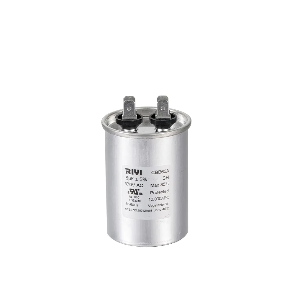
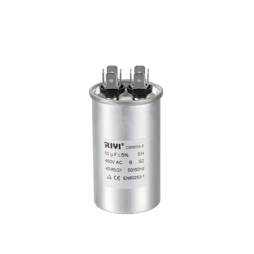
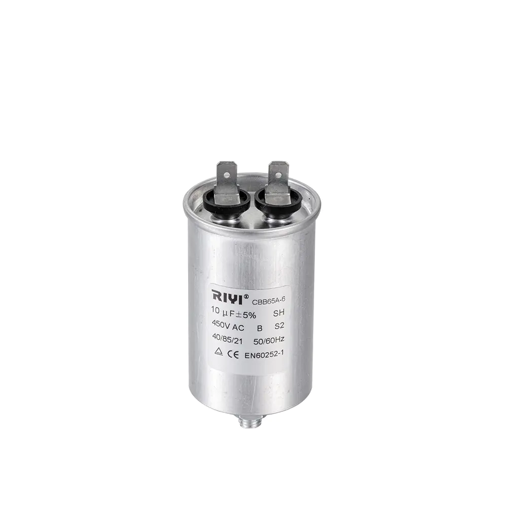
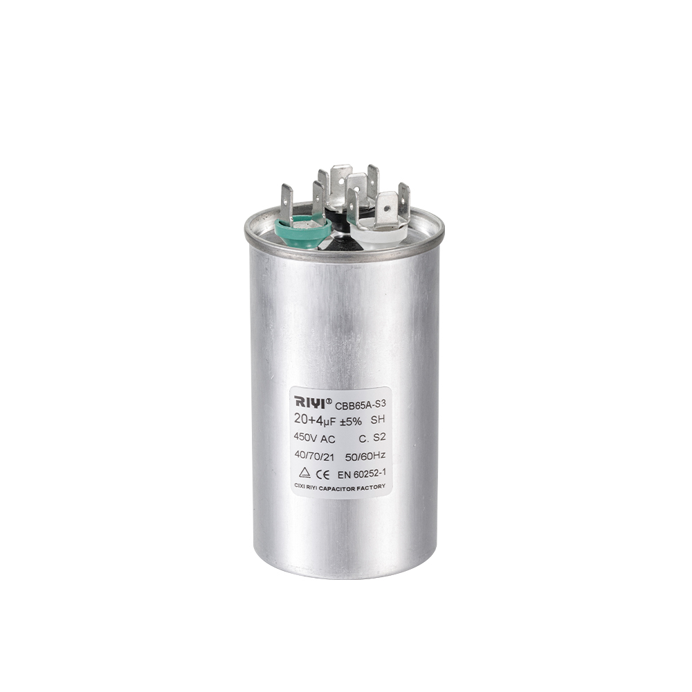
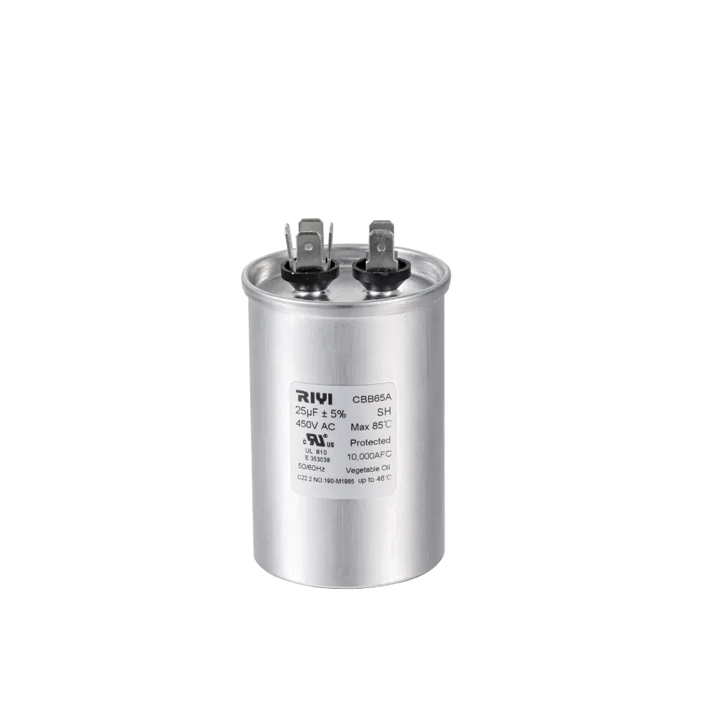
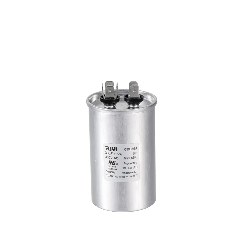
As a capacitor manufacturer, we regularly see replacement mistakes caused by mixed terminal layouts and diameter mismatches. CBB65 series round aluminum capacitors cover the common HVAC replacement range. A few practical examples from our standard catalog:
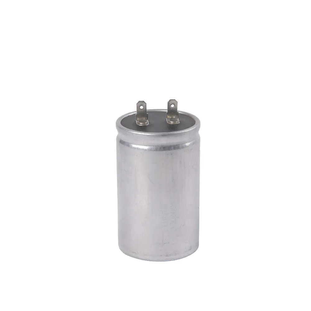
- For a compressor side that needs 40 µF, the 40 µF 450 VAC aluminum-housing explosion-proof capacitor
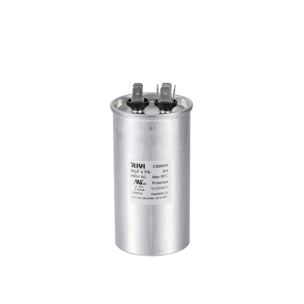 Custom AC Cbb65 40uf 450v S2 Explosion-Proof Aluminum Housing 2+4 terminal InserCixi Riyi Capacitor is China custom Cbb65 40uf 450v S2 Explosion-Proof Aluminum Housing 2+4 terminal. CBB65 Explosion-Proof Capacitor Ins...View Product → keeps the same round-can footprint as most OEM dual capacitors and uses 2-4 insert terminals for a direct swap.
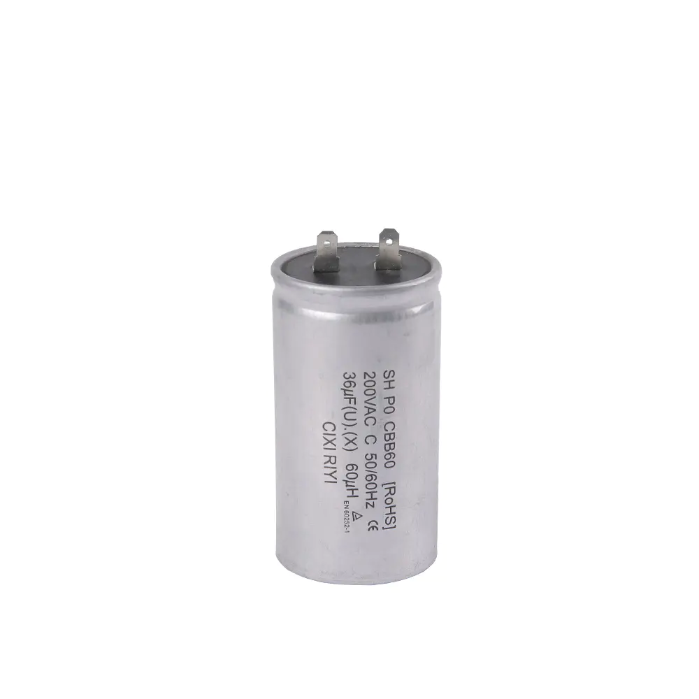
 - If the original compressor value is 35 µF, the 35 µF 450 VAC explosion-proof capacitor
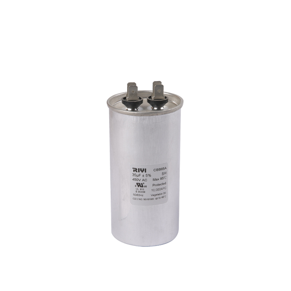 Custom AC Cbb65 35uf 450v S2 Explosion-Proof Aluminum Housing 2+2 terminal InserCixi Riyi Capacitor is China custom Cbb65 35uf 450v S2 Explosion-Proof Aluminum Housing 2+2 terminal. CBB65 Explosion-Proof Capacitor Ins...View Product → matches the standard 2-2 terminal arrangement found on many residential condensing units.
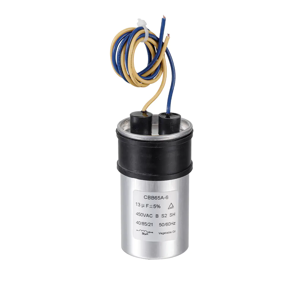
 - Where the fan motor needs a separate small run value, an 8 µF 450 VAC lead-type capacitor with inductance
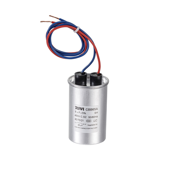 Custom AC Cbb65 8uf 450v C S2 With Inductance, Lead Lead CBB65 Explosion-Proof CCixi Riyi Capacitor is China custom Cbb65 8uf 450v C S2 With Inductance, Lead. CBB65 Explosion-Proof Capacitor Lead manufacturers and OEM...View Product → can be installed alongside the main can to restore reliable fan rotation.
When in doubt, take the failed capacitor with you when ordering the replacement. Comparing the physical height, diameter, and terminal spacing side by side prevents the most common fitment errors.
Frequently Asked Questions
Can I test a dual run capacitor while it is still connected in the circuit?
You can, but the reading will not be trustworthy. The compressor and fan motor windings run parallel to the capacitor, so the meter sees a combination of the capacitor and the low-resistance windings. For a dependable result, disconnect at least one wire from each terminal or pull the capacitor out entirely.
What does 35/5 µF mean on a dual run capacitor?
The larger number 35 µF serves the compressor, and the smaller number 5 µF serves the condenser fan motor. When testing, C–HERM should approximate the larger value and C–FAN should approximate the smaller value.
What is the acceptable tolerance for a motor run capacitor?
Most manufacturers print a tolerance of ±5%, ±6%, or ±10% on the label. When no tolerance is listed, HVAC technicians commonly treat ±6% as acceptable and anything beyond ±10% as a confirmed failure. A 40 µF section should therefore ideally read between 37.6 and 42.4 µF.
My multimeter has no capacitance mode. Is there another way to test?
You can use the resistance mode to identify a shorted or open capacitor, and you can check for continuity between the terminals and the case. However, you will not be able to measure whether a 5 µF fan section has degraded to 4 µF. A capacitance mode meter is inexpensive and strongly recommended for accurate diagnosis.
How long does a dual run capacitor normally last?
A typical metallized polypropylene run capacitor survives roughly 5 to 10 years in residential service. Heat is the dominant factor: every 8–10°C above the rated temperature roughly halves the expected life. In a condenser that operates in direct sun, the capacitor compartment can easily reach 60–70°C on a hot afternoon.
Should I replace the capacitor if it measures within tolerance but the fan still does not start?
If the static capacitance looks normal, check the fan motor itself, the contactor, and the wiring connections. A capacitor can also lose effective capacitance at operating temperature even when a cold bench reading looks fine. In that situation, testing the motor directly and inspecting the contactor points usually reveals the real fault. You can follow the same logic covered in our guide on measuring and replacing AC motor capacitors.
Final Recommendation
Testing a dual run capacitor is one of the first diagnostics an HVAC professional runs because capacitor degradation causes a large share of no-cooling calls. With a multimeter that has capacitance mode, a 20 kΩ resistor, and the terminal-by-terminal method described above, a careful homeowner can tell the difference between a weak capacitor and a problem elsewhere in the system.
Remember the three rules: always disconnect power and discharge before touching anything, always test both the C–HERM and C–FAN sections, and always replace with a capacitor that matches the original microfarad and voltage ratings. Keep this in mind as a routine check, not a luxury. A thirty-second measurement can save an expensive compressor from repeated hard starts and eventual burnout.

 +86-13600614158
 +86-0574-63223385
 Zonghan Street,Cixi City,Zhejiang Province,China.