 简体中文
简体中文 English
 Español
 عربى
عربىContent
- 1 What Is a 1 Microfarad Capacitor and Why Does It Matter
- 2 The Microfarad Unit Explained: Scale, Conversion, and Practical Reference
- 3 How the CBB60 Capacitor Works and Where 1 µF Fits In
- 4 Key Specifications to Check When Selecting a 1 Microfarad CBB60 Capacitor
- 5 CBB60 Capacitor vs. Other Motor Capacitor Types
- 6 Applications Where a 1 Microfarad Capacitor Is the Right Choice
- 7 How to Test a 1 Microfarad Capacitor with a Multimeter
- 8 Signs a 1 µF CBB60 Capacitor Has Failed
- 9 Step-by-Step Guide to Replacing a 1 µF CBB60 Capacitor
- 10 Storing, Handling, and International Standards for CBB60 Capacitors
What Is a 1 Microfarad Capacitor and Why Does It Matter
A 1 microfarad (1 µF) capacitor stores one millionth of a farad of electrical charge. That might sound trivially small, but in practice it represents one of the most versatile capacitance values in electronics — useful across timing circuits, signal coupling, audio filtering, power supply decoupling, and motor phase-shift applications. When someone refers to a "1 µF cap," they are typically pointing to a component that handles low-to-mid frequency tasks with precision and minimal energy loss.
To put the scale in context: one farad is a massive quantity of capacitance almost never seen in discrete components. One microfarad equals 10⁻⁶ farads, and sits comfortably between picofarad-range ceramic caps used for RF filtering and the hundreds-of-microfarad electrolytic capacitors used in bulk power smoothing. That middle ground is exactly where 1 µF shines — capable enough to interact meaningfully with low-frequency AC signals and compact enough to appear in everything from smartphone circuits to washing machine motor boards.
The CBB60 capacitor family, built around metallized polypropylene film technology, frequently appears in the 1 µF to 100 µF range. A 1 µF CBB60 capacitor is typically employed in light-duty motor auxiliary windings, fan control boards, and low-power pump circuits where a stable, long-life film capacitor outperforms cheaper alternatives. Understanding how the 1 microfarad value behaves in these contexts is the foundation for selecting, testing, and replacing these components correctly.
The Microfarad Unit Explained: Scale, Conversion, and Practical Reference
The farad (F) is the SI base unit for electrical capacitance. Because one farad is enormous by practical standards — a 1 F capacitor at 5 V would store enough charge to light an LED for hours — engineers work primarily with subdivisions. The most common are:
- Microfarad (µF or uF): 1 × 10⁻⁶ F — used in motor capacitors, audio coupling, and power supply filtering
- Nanofarad (nF): 1 × 10⁻⁹ F — used in timing circuits and high-frequency filters; 1 µF = 1,000 nF
- Picofarad (pF): 1 × 10⁻¹² F — used in RF, antenna circuits, and crystal oscillators; 1 µF = 1,000,000 pF
A 1 µF capacitor labeled "105" on its body (common for ceramic multilayer types) uses code notation: the first two digits give the mantissa (10), and the third digit gives the exponent of 10 in picofarads (5 = 10⁵ pF = 100,000 pF = 0.1 µF). A part labeled "1µF" directly, or carrying a "1.0" alongside the µF symbol, is unambiguous. Always read the unit marker carefully — confusing µF with nF on a motor capacitor can result in a component with 1,000 times too little capacitance, causing the motor to fail to start entirely.
For motor applications, capacitance values typically run between 1 µF and 100 µF depending on motor size. A ceiling fan might require 1 µF to 5 µF; a small single-phase pump motor may need 4 µF to 16 µF; a full-size washing machine drum motor commonly uses 8 µF to 25 µF. The 1 µF value, therefore, corresponds to the smallest practical motor capacitor territory — auxiliary fans, small water pumps, and light-load induction motors
How the CBB60 Capacitor Works and Where 1 µF Fits In
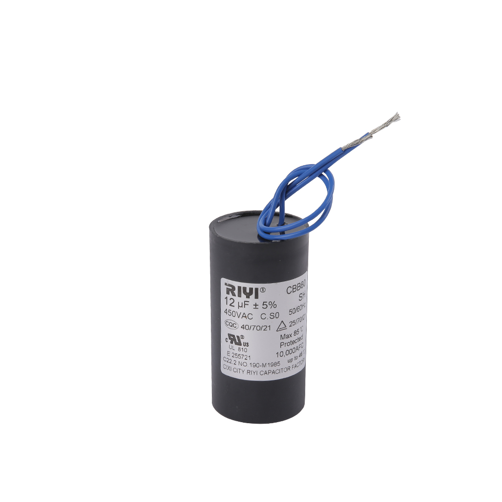
The CBB60 capacitor is a cylindrical AC motor run capacitor built around a metallized polypropylene (MPP) film dielectric. The "CBB" designation follows the Chinese national standard (GB/T 3667) for metallized film capacitors used in AC motor circuits, while "60" identifies the cylindrical form factor. These capacitors are rated for continuous AC duty — unlike electrolytic start capacitors that are only energized for a second or two at startup, a CBB60 capacitor remains in circuit and energized throughout the entire motor run cycle.
The core function of a CBB60 capacitor in a single-phase motor is phase shifting. A single-phase AC power supply cannot on its own generate a rotating magnetic field — it only produces an oscillating one. By connecting a capacitor in series with the auxiliary (start) winding, the current through that winding is shifted approximately 90 degrees relative to the main winding current. This phase difference creates a two-phase approximation sufficient to generate a rotating magnetic field and produce starting torque.
At 1 µF, a CBB60 capacitor produces a relatively modest phase-shift contribution, suited to motors with low starting torque requirements and small auxiliary windings. Its reactance (Xc) at 50 Hz can be calculated as:
Xc = 1 / (2π × f × C) = 1 / (2π × 50 × 0.000001) ≈ 3,183 ohms
At 60 Hz, that drops to approximately 2,653 ohms. This high impedance means a 1 µF capacitor allows only a small reactive current to flow — suitable for small motors where the auxiliary winding resistance and inductance are themselves high. Pairing a 1 µF CBB60 capacitor with a motor that requires 10 µF would result in severely reduced starting torque, possible humming, overheating of the auxiliary winding, and eventually motor failure.
Self-Healing Properties of Metallized Film
One of the defining advantages of the CBB60 construction is self-healing. When a microscopic defect or local dielectric breakdown occurs, the thin aluminum or zinc metallization around the fault vaporizes almost instantly due to the energy released. This isolates the defect and restores the dielectric, preventing catastrophic short circuits. A single self-healing event causes a negligible reduction in capacitance — often less than 0.01% — meaning the capacitor continues to function reliably even after numerous minor fault events over its operating life.
This self-healing property is one reason CBB60 capacitors are preferred over paper or aluminum electrolytic types for continuous motor run duty. A typical high-quality CBB60 capacitor is rated for 60,000 hours or more of continuous operation at rated temperature, compared to 2,000–5,000 hours for typical aluminum electrolytic capacitors under similar conditions.
Key Specifications to Check When Selecting a 1 Microfarad CBB60 Capacitor
Choosing the right 1 µF capacitor for a motor application goes beyond matching the capacitance number. Several interdependent specifications determine whether the component will perform safely and last its rated lifespan.
| Specification | Typical Range for CBB60 | What to Look For |
|---|---|---|
| Capacitance | 1 µF – 100 µF | Match motor nameplate exactly |
| Tolerance | ±5% or ±10% | ±5% preferred for precision applications |
| Voltage Rating (VAC) | 250 VAC, 370 VAC, 450 VAC | Equal or higher than circuit voltage; never lower |
| Frequency | 50 Hz / 60 Hz | Must match grid frequency of installation |
| Operating Temperature | -25°C to +70°C or +85°C | Higher-rated grades for enclosed or hot environments |
| Dissipation Factor (tan δ) | < 0.001 at 1 kHz | Lower = less heat generation under load |
| Insulation Resistance | > 3,000 MΩ (new) | Higher is better; drops with age and heat |
| Safety Class | P2 standard; SH enhanced | SH grade preferred for long-life critical applications |
| Certifications | UL, cUL, CE, RoHS, VDE | Match the target market's requirements |
Voltage Rating: Safe to Go Higher, Never Lower
A common question when replacing a 1 µF CBB60 capacitor is whether a higher voltage-rated unit can substitute for the original. The answer is yes — replacing a 250 VAC unit with a 450 VAC one is perfectly acceptable and actually provides a larger safety margin. The voltage rating represents the maximum voltage the dielectric can withstand continuously without breakdown. Using a 450 VAC capacitor on a 230 V circuit simply means the dielectric operates at well below its stress limit, which often extends service life. Never substitute a lower voltage rating: a 250 VAC capacitor on a 370 V circuit is likely to fail rapidly and could do so catastrophically.
Capacitance Tolerance and Motor Performance
Motor designers specify capacitance values with tolerances, commonly ±5% or ±10%, because the capacitor interacts with the motor's winding impedance to create the phase shift. A 1 µF capacitor with ±10% tolerance could measure anywhere from 0.9 µF to 1.1 µF. For most small fan or pump motors, this range is acceptable. However, for precision motor control applications — variable-speed drives, HVAC scroll compressors, or medical equipment — tighter tolerance (±5% or even ±2%) is warranted to maintain consistent torque and efficiency across the service temperature range.
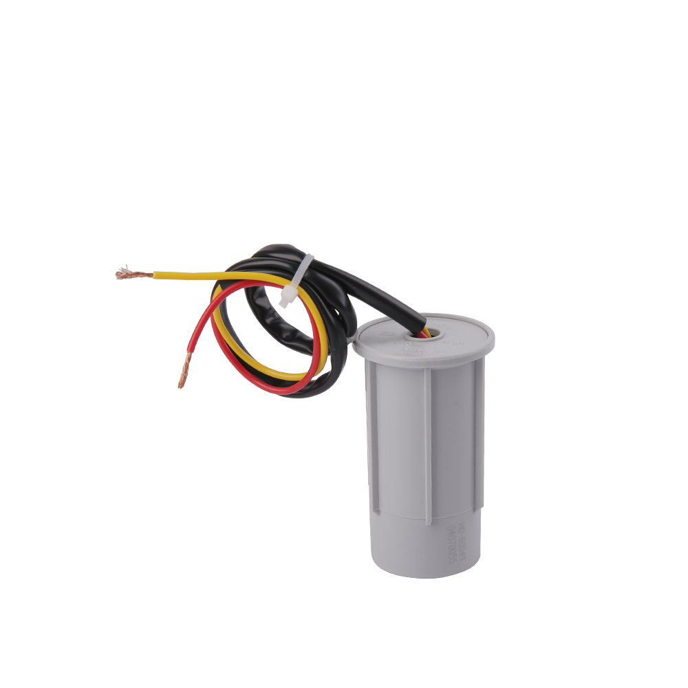
.jpg)
CBB60 Capacitor vs. Other Motor Capacitor Types
The CBB60 is not the only motor capacitor standard. Understanding where it sits relative to its siblings helps clarify which one a given application needs — and where a 1 µF value makes most sense.
CBB60 vs. CBB61
Both the CBB60 and CBB61 use metallized polypropylene film dielectric and are governed by IEC 60252-1. The sole structural difference is form factor: CBB60 is cylindrical, CBB61 is rectangular (box-shaped). Electrically, a CBB61 1 µF 250 VAC unit is interchangeable with a CBB60 1 µF 250 VAC unit, provided the safety class, climate category, and terminal configuration all match. The practical consideration is mechanical fit — whether the mounting bracket in the appliance accommodates a cylinder or a flat box.
CBB60 vs. CBB65
The CBB65 is a heavier-duty variant designed specifically for air conditioning compressor motors and high-ambient-temperature environments. It typically has a wider temperature rating (up to 85°C or 95°C) and is often filled with flame-retardant resin for added safety under high-stress operating conditions. For a 1 µF application in a small fan or low-power pump, the CBB65 would be overkill in terms of size and cost. However, if the 1 µF capacitor is located inside an enclosed compressor housing or subject to continuous high-temperature cycling, the CBB65's thermal margin becomes a genuine engineering advantage.
CBB60 vs. CD60 Electrolytic Start Capacitor
The CD60 is an aluminum electrolytic capacitor designed exclusively for motor starting duty — it is energized only during the startup phase (typically 1–3 seconds) and then disconnected by a centrifugal switch or electronic relay. CD60 capacitors come in much higher capacitance values (50 µF to 1,200 µF) because their job is to provide a massive initial torque boost. A 1 µF value would never appear in a CD60 start capacitor — the capacitance is simply too low to provide meaningful starting torque for any motor large enough to require a start capacitor. The 1 µF CBB60, by contrast, is a run capacitor that stays in circuit continuously.
| Type | Form Factor | Duty | Typical µF Range | 1 µF Available? |
|---|---|---|---|---|
| CBB60 | Cylindrical | Continuous run | 1–100 µF | Yes |
| CBB61 | Rectangular | Continuous run | 1–100 µF | Yes |
| CBB65 | Cylindrical / oval | Continuous run (high temp) | 5–70 µF | Rarely |
| CD60 | Cylindrical | Start only (intermittent) | 50–1,200 µF | No |
Applications Where a 1 Microfarad Capacitor Is the Right Choice
The 1 µF value covers a broader range of circuit types than motor applications alone. Here is a structured look at where this specific capacitance value delivers optimal performance.
Small Single-Phase Motor Auxiliary Winding Circuits
Ceiling fans, exhaust fans, small table fans, and low-wattage centrifugal pumps are the most common homes for a 1 µF capacitor in motor duty. These motors have small auxiliary windings with relatively high impedance, meaning a large capacitor would cause overcurrent in the auxiliary circuit. A 1 µF unit provides just the right reactive current magnitude to create effective phase shift without stressing the winding insulation. Some multi-speed fan motors use capacitor networks — for example, a 1 µF and a 2 µF capacitor switched in different combinations — to achieve three distinct speed settings.
Timing and Oscillator Circuits
In the classic 555 timer IC circuit, the time constant is set by the formula t = 1.1 × R × C. With a 1 µF capacitor and a 100 kΩ resistor, the output pulse width is approximately 0.11 seconds — a commonly needed interval in industrial timers, relay delay circuits, and sequential control systems. Changing from a 1 µF to a 10 µF capacitor in the same circuit multiplies that delay tenfold to 1.1 seconds. This makes 1 µF a natural "unit step" for timing circuit design, offering an intuitive scale for calculation.
Audio Signal Coupling and Filtering
In audio electronics, a 1 µF capacitor in a coupling role creates a high-pass filter. Paired with a 10 kΩ load, the -3 dB cutoff frequency is approximately 16 Hz — right at the bottom of the audible range. This makes 1 µF coupling capacitors common in audio amplifier designs where the goal is to pass all audible frequencies while blocking any DC offset that would shift the operating point of subsequent stages. Film capacitors — including the polypropylene film used in CBB60 construction — are often favored for audio coupling due to their low distortion compared to electrolytic types.
Power Supply Decoupling
In mixed-signal and analog power supply design, a 1 µF decoupling capacitor placed close to an IC's power pin suppresses mid-frequency noise in the 100 kHz to several MHz range that a larger bulk electrolytic cannot handle quickly enough. It is common practice to pair a 100 µF electrolytic (bulk) with a 1 µF ceramic or film capacitor (mid-frequency) and a 100 nF ceramic (high-frequency) at each supply rail, covering three decades of frequency with three components.
Variable-Speed Fan and Motor Control Boards
Electronic speed controllers for ceiling fans and small appliance motors frequently include a 1 µF polypropylene film capacitor in their snubber circuits. These snubbers suppress voltage spikes generated when inductive motor windings are switched by TRIAC or transistor devices. Without the snubber capacitor, these spikes can exceed several hundred volts in microseconds, destroying the switching device. A 1 µF capacitor paired with a series resistor (often 10–100 Ω) is a standard snubber configuration for motors in the 50–500 W power range.
How to Test a 1 Microfarad Capacitor with a Multimeter
Verifying that a 1 µF capacitor is functioning correctly before or after installation is straightforward with a modern digital multimeter that includes a capacitance measurement function. The process takes less than five minutes and can confirm whether a suspected faulty component is actually defective — or whether the fault lies elsewhere in the circuit.
- Disconnect power: Never test a capacitor while the circuit is energized. For capacitors in motor circuits, also wait 30 seconds after power removal before touching terminals — residual charge can persist.
- Discharge the capacitor: For a 1 µF capacitor, a 10 kΩ resistor bridged across the terminals for 2–3 seconds is sufficient to bring the residual voltage to a safe level. Larger capacitors require longer discharge times.
- Set the multimeter: Switch to the capacitance (CAP or µF) measurement mode. Some meters require selecting a range; choose the lowest range that can display 1 µF, typically the 2 µF or 10 µF range.
- Connect and measure: Touch the meter probes to the capacitor terminals. For non-polarized film capacitors like CBB60 types, polarity does not matter. For electrolytic capacitors, match red to positive and black to negative.
- Interpret the reading: A healthy 1 µF capacitor should read between 0.9 µF and 1.1 µF (within ±10% tolerance). A reading more than 10% below the rated value indicates deterioration. A reading of 0 or "OL" (open circuit) means the dielectric has broken down and the part must be replaced.
If your multimeter does not have a capacitance function, an alternative method is the charge-time test: charge the capacitor through a known resistor from a DC supply and measure the time to reach 63.2% of supply voltage (one time constant, τ = RC). For a 1 µF capacitor and a 10 kΩ resistor, τ = 0.01 seconds. This method requires an oscilloscope or fast voltmeter and is generally reserved for technicians with more advanced equipment.
Signs a 1 µF CBB60 Capacitor Has Failed
Capacitor failure in motor circuits rarely happens instantaneously. More often, the capacitance gradually drifts downward as the dielectric ages — a process accelerated by heat, voltage spikes, and high humidity. Recognizing the early symptoms of capacitor degradation can save a motor from permanent winding damage.
- Motor hums but will not start — the most common symptom of a completely failed run capacitor. The motor receives power and the main winding energizes, but without the phase-shifted current from the auxiliary winding, no rotating magnetic field forms and the rotor stays still.
- Reduced motor speed — a partially degraded capacitor may allow the motor to start and run, but with reduced torque and below-rated speed. A fan running noticeably slower than normal often has a capacitor at 70–80% of its rated value.
- Excessive motor heat — when the capacitor's capacitance falls, the auxiliary winding current becomes unbalanced relative to the main winding, causing higher-than-normal current in both windings and elevated motor temperature.
- Tripped breakers during motor startup — a deteriorated capacitor causes the motor to draw much higher inrush current at startup, sometimes enough to trip the circuit breaker that protects the circuit.
- Visible physical damage — bulging of the capacitor casing, cracks in the resin end seal, or brown discoloration are all signs of thermal overstress. Any capacitor showing physical damage should be replaced regardless of its measured capacitance value.
When in doubt, replacement is inexpensive relative to the cost of a burned motor. A quality 1 µF CBB60 capacitor typically costs less than $5. A replacement motor or a service call to diagnose a motor failure caused by neglecting a faulty capacitor costs significantly more.
Step-by-Step Guide to Replacing a 1 µF CBB60 Capacitor
Replacing a run capacitor in a small motor or fan is a straightforward repair that most technically inclined homeowners or maintenance technicians can perform safely. The critical safety rule is simple: always disconnect power and verify it is off before touching any component.
- Disconnect the appliance from its power source. For hardwired equipment, switch off the circuit breaker and verify with a non-contact voltage tester.
- Photograph the original capacitor and its wiring connections before removing anything. This provides a reference for reconnecting the replacement correctly.
- Discharge the capacitor using a resistor across its terminals. Although a 1 µF capacitor stores only a small amount of energy, this step is good practice before handling.
- Note the exact specifications printed on the capacitor body: capacitance (µF), voltage rating (VAC), frequency (Hz), and any additional codes (SH, P2, climate category). These determine the replacement part.
- Obtain a replacement with the same capacitance, same or higher voltage rating, same or wider temperature rating, and the same terminal configuration (spade quick-connect, wire leads, or screw terminals).
- Connect the replacement using the photograph as reference. For standard two-terminal CBB60 capacitors, polarity is not relevant — either terminal can connect to either wire.
- Secure the capacitor in its mounting bracket or clip. CBB60 cylindrical capacitors typically mount with a metal or plastic strap around the body.
- Restore power and test the motor for correct startup and running behavior. If the motor still hums or fails to start, check the centrifugal switch, thermal overload, or motor windings before assuming another capacitor failure.
Storing, Handling, and International Standards for CBB60 Capacitors
Capacitors are generally robust components, but improper storage can degrade their performance before they are ever installed. Film capacitors like the CBB60 series are less sensitive to storage conditions than aluminum electrolytic types, but a few precautions extend shelf life significantly.
- Store in a cool, dry environment with temperatures between 5°C and 40°C and relative humidity below 75%. High humidity over extended periods can permeate the plastic casing and introduce moisture into the dielectric, reducing insulation resistance.
- Avoid direct sunlight or UV exposure. UV radiation degrades polypropylene over time, which can affect the film's electrical properties.
- Keep away from corrosive chemicals, solvents, and salt spray environments. The metallic terminal pins and end caps can corrode, increasing contact resistance.
- Film capacitors like CBB60 types do not require periodic reforming (re-energizing) the way aluminum electrolytic capacitors do, making them more forgiving in long-term storage. A CBB60 1 µF capacitor stored properly for five years should perform identically to a fresh one.
International Standards and Certifications
Quality CBB60 capacitors intended for use in consumer appliances, HVAC equipment, and industrial motors are manufactured and tested against established international standards. Purchasing from certified sources ensures the component performs as labeled and includes the necessary safety protections.
- IEC 60252-1: The primary international standard for AC motor capacitors. Defines test methods for capacitance, tan delta, insulation resistance, voltage endurance, and temperature performance.
- GB/T 3667: The Chinese national standard equivalent to IEC 60252-1, which serves as the direct design reference for CBB-series capacitors.
- UL 810: The North American standard for capacitors, required for products sold in the United States. UL-listed CBB60 capacitors carry the UL mark and cUL designation for Canada.
- VDE: The German electrical engineering association certification required for products in the European market. A VDE-marked capacitor has passed rigorous independent testing.
- RoHS compliance: Ensures the capacitor is free of hazardous substances including lead, mercury, cadmium, and certain brominated flame retardants — required for products sold within the European Union.
When sourcing a 1 µF CBB60 capacitor for commercial or industrial use, always request the relevant certifications from the supplier. Counterfeit or substandard capacitors that falsely claim ratings are a documented problem in the market — a capacitor labeled 1 µF / 450 VAC that is actually rated for only 250 VAC will fail under normal operating conditions, potentially causing motor damage or even fire in enclosed housings.


 +86-13600614158
 +86-0574-63223385
 Zonghan Street,Cixi City,Zhejiang Province,China.