10nF to µF: The Direct Answer and Why It Matters for Capacitor Selection
10 nanofarads (nF) equals 0.01 microfarads (µF). The conversion is straightforward: 1 µF = 1,000 nF, so dividing 10 by 1,000 gives you 0.01 µF. While the arithmetic is simple, understanding where this value sits in the broader capacitance spectrum — and how it relates to components like the CBB60 capacitor — is critical for engineers, technicians, and procurement professionals who need to match the right capacitor to the right application.
Capacitance units trip people up constantly. Datasheets, supplier catalogs, and circuit diagrams use nF, µF, and pF interchangeably depending on the manufacturer's convention, the country of origin, and the era the document was written. A 10 nF capacitor labeled in one datasheet might appear as 0.01 µF or even 10,000 pF in another — all three describe exactly the same component. Knowing how to move fluently between these units prevents costly ordering errors and ensures the component you install is the one the design actually calls for.
Capacitance Unit Conversion: The Full Reference Table
Before diving deeper into applications, here is a complete conversion reference covering the range from picofarads to farads. This table covers the values most commonly encountered in industrial and consumer electronics, including the ranges where CBB60 capacitors and film capacitors operate.
| Value in nF |
Value in µF |
Value in pF |
Common Application Context |
| 1 nF |
0.001 µF |
1,000 pF |
RF filters, timing circuits |
| 10 nF |
0.01 µF |
10,000 pF |
Bypass caps, signal coupling |
| 100 nF |
0.1 µF |
100,000 pF |
Decoupling, motor start assist |
| 1,000 nF |
1 µF |
1,000,000 pF |
Audio crossovers, power supply filtering |
| 10,000 nF |
10 µF |
— |
Bulk filtering, motor run capacitors (smaller motors) |
Table 1: Capacitance unit conversions across the nF, µF, and pF scales with typical application contexts
The conversion formula is always the same: µF = nF ÷ 1,000. Going the other direction: nF = µF × 1,000. Keep this relationship in mind whenever you encounter a value marked in one unit on a diagram and need to verify it against a component marked in another.
Where 10nF Sits in the Capacitance Spectrum
At 0.01 µF, a 10 nF capacitor occupies the lower-middle range of practical capacitance values. It is well above the sub-picofarad stray capacitances found in PCB traces (which typically run 1–5 pF per centimeter of trace), and well below the multi-microfarad bulk storage capacitors used in power supplies and motor starting circuits.
High-Frequency Signal Work: Where 10nF Excels
In signal processing, 10 nF capacitors appear frequently in RC timing networks, coupling stages, and bypass applications where the goal is to pass AC signals while blocking DC offsets. The impedance of a 10 nF capacitor at 1 kHz is approximately 15,900 ohms, dropping to 1,590 ohms at 10 kHz and 159 ohms at 100 kHz. These characteristics make it useful for mid-to-high-frequency filtering — but completely unsuitable for the motor-starting function where CBB60 capacitors are typically deployed.
Industrial Power Applications: The Jump to µF Territory
Motor run and motor start applications sit at the opposite end of the capacitance scale from 10 nF. A standard single-phase induction motor — the kind used in water pumps, washing machines, air compressors, and pool pumps — typically requires run capacitances ranging from 1 µF to 100 µF, depending on motor wattage and design. This is 100 to 10,000 times larger than 10 nF. A typical 750W submersible pump motor might call for a 20–30 µF run capacitor, while a 2.2 kW air compressor motor might need 60–80 µF. The CBB60 capacitor series covers exactly this range, manufactured specifically for these demanding AC motor applications.
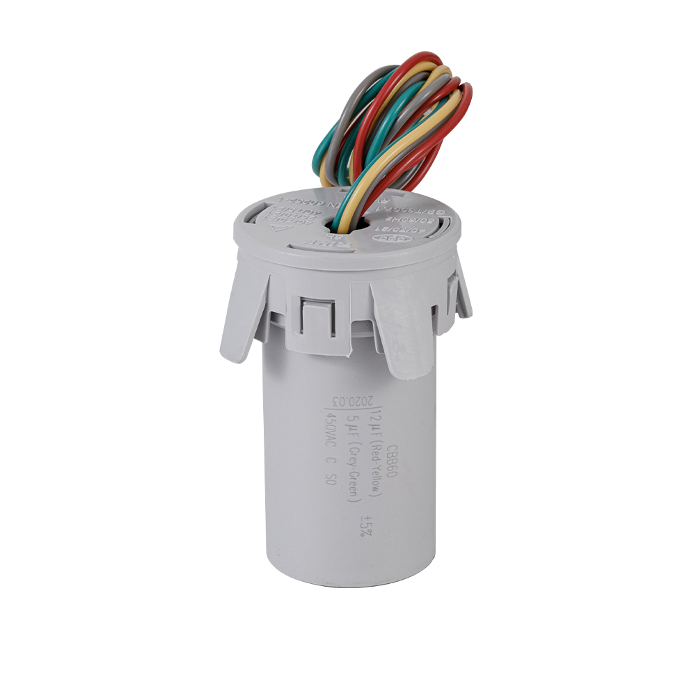
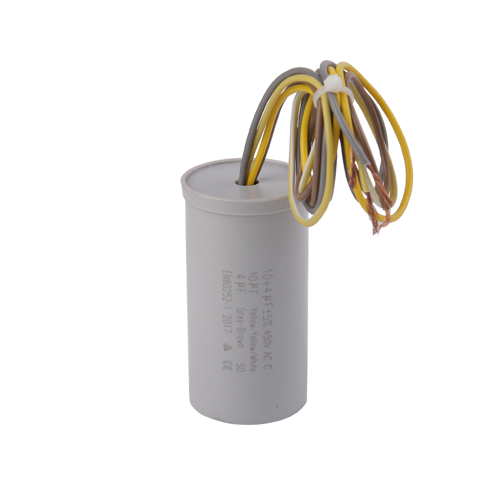
CBB60 Capacitor: Specifications, Construction, and Why This Type Dominates Motor Applications
The CBB60 capacitor is a polypropylene film capacitor designed for AC motor operation, particularly in single-phase induction motors requiring a permanent run capacitor on the auxiliary winding. The "CBB" designation follows the Chinese standard GB/T 3667 and indicates a metallized polypropylene film dielectric — a construction that combines high dielectric strength, low dielectric loss, and excellent self-healing properties.
Standard CBB60 Specifications at a Glance
| Parameter |
Typical Range |
Notes |
| Capacitance Range |
1 µF – 100 µF |
Most common: 5–50 µF for pump/compressor motors |
| Rated Voltage |
250 VAC / 450 VAC |
450VAC for 380V industrial systems |
| Frequency |
50 Hz / 60 Hz |
Must match local grid frequency |
| Operating Temperature |
-25°C to +85°C |
Some grades rated to +105°C |
| Capacitance Tolerance |
±5% (J) / ±10% (K) |
Motor start caps may allow ±20% |
| Dissipation Factor (tan δ) |
≤ 0.001 at 1 kHz |
Low loss = low heat generation in service |
| Enclosure |
Cylindrical plastic case, epoxy-sealed |
IP44 moisture resistance standard |
| Leads |
Two wire terminals (non-polar) |
Non-polarized; either lead can be positive |
Table 2: Key specifications of the CBB60 capacitor series used in AC motor applications
Notice that even the smallest CBB60 capacitor — 1 µF — is 100 times larger than 10 nF. This comparison clarifies why unit confusion between nF and µF is so consequential: ordering a component an order of magnitude too small will result in a motor that fails to start or runs with significant torque deficiency.
Self-Healing Metallized Film: The Technology Behind CBB60 Reliability
One of the defining advantages of the CBB60 capacitor is its metallized polypropylene film construction. Rather than using a separate metal foil electrode, the metallized film type deposits an extremely thin layer of aluminum or zinc directly onto the polypropylene film substrate — typically just 20–50 nanometers thick. This has a profound effect on failure behavior.
When a dielectric breakdown occurs at a localized defect — from a momentary voltage spike, a contamination particle, or a manufacturing micro-void — the intense heat at the fault point vaporizes the surrounding metal layer within microseconds. The damaged area becomes self-isolated, the dielectric film re-establishes itself, and the capacitor continues to function with only a negligible reduction in capacitance. This self-healing mechanism means that a CBB60 capacitor can survive thousands of minor breakdown events over its service life without catastrophic failure.
How This Compares to Electrolytic Capacitors
Aluminum electrolytic capacitors — common in power supplies, audio equipment, and some motor start applications — cannot self-heal. Once the oxide dielectric layer breaks down, electrolyte vaporizes, internal pressure builds, and the component fails (sometimes explosively, which is why electrolytics have pressure-relief vents). They also degrade from electrolyte evaporation over time, with typical service lives of 2,000–10,000 hours at rated temperature. A well-manufactured CBB60 capacitor, operating within its rated conditions, can deliver service lives exceeding 100,000 hours — more than 11 years of continuous operation.
How to Select the Right CBB60 Capacitor Value: Moving from nF to the Correct µF Rating
Converting 10 nF to µF gives you 0.01 µF — far too small for any motor application. When replacing or specifying a CBB60 capacitor, the correct µF value is determined by the motor's nameplate or service documentation, not by guesswork or approximation. Here is the structured process for arriving at the correct specification:
- Read the motor nameplate — most AC induction motors have the required capacitance (in µF) and voltage (VAC) printed directly on the label or on the existing capacitor body.
- If the nameplate is missing or illegible, consult the motor winding specification — the correct run capacitance is determined by the auxiliary winding impedance and the desired phase angle correction.
- Match voltage rating first. A CBB60 capacitor rated at 250 VAC must not be used on a 380V supply. Always use a 450 VAC rated unit on 380V systems with a minimum 20% safety margin.
- Verify the physical dimensions. CBB60 capacitors in the 10–60 µF range typically measure 30–45mm in diameter and 55–80mm in height. Ensure the replacement fits the existing mounting bracket or housing.
- Check frequency compatibility (50 Hz vs. 60 Hz). While the capacitance value itself is frequency-independent, the reactive current drawn by the motor circuit changes with frequency, and some CBB60 variants are specifically tested and rated for one frequency.
- Confirm tolerance grade. For motor run applications, ±5% (J grade) is preferred. Larger tolerance (±10% or ±20%) may be acceptable for motor start capacitors that only operate briefly during startup, but run capacitors benefit from tighter tolerance for consistent performance.
Estimating Capacitance from Motor Power (Rule of Thumb)
When no nameplate data is available, engineers sometimes use empirical formulas to estimate the required run capacitance. One widely used approximation for single-phase induction motors is:
C (µF) ≈ (P × 1,000) / (U² × f × cos φ × η)
Where P = motor power in watts, U = supply voltage in volts, f = frequency in Hz, cos φ = power factor (typically 0.8–0.9), η = efficiency (typically 0.8–0.85)
For a 550W motor on 220V, 50Hz supply with cos φ = 0.85 and η = 0.82, this yields approximately 16–20 µF — well within the typical CBB60 product range. Note that this is an estimation tool only; always verify against motor documentation when possible.
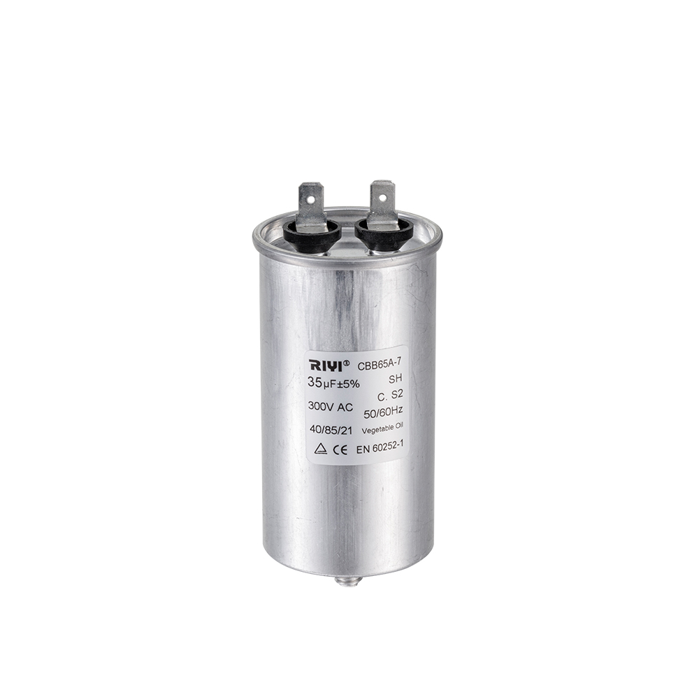
CBB60 vs. Other Capacitor Types: Application Boundaries and Substitution Rules
Not all capacitors rated in µF are interchangeable with CBB60 units, even if the capacitance value matches. The dielectric material, voltage rating, current handling capability, and frequency response all determine whether a given capacitor is suitable for AC motor duty. Here is how the CBB60 compares to the most common alternatives:
CBB60 vs. CBB61
The CBB61 is also a metallized polypropylene film capacitor, but designed for fan motor applications where a smaller, flat form factor fits inside the motor housing. CBB61 capacitors are typically rated for lighter duty cycles and lower capacitance values (0.5–20 µF) compared to CBB60 units (1–100 µF). Do not substitute a CBB61 for a CBB60 in pump or compressor applications — the current rating is insufficient for the higher-inrush conditions of these motors.
CBB60 vs. Electrolytic Start Capacitors
Electrolytic motor start capacitors (often with 150–600 µF ratings and 125–250 VAC ratings) are used only for the brief starting interval — typically 0.5 to 3 seconds — and are disconnected by a centrifugal switch once the motor reaches ~75% of synchronous speed. They cannot handle continuous AC current. A CBB60 capacitor, by contrast, is designed for continuous AC operation at rated frequency and voltage. Never use a CBB60 as a start capacitor for motors requiring high-capacitance starts (compressor and large pump motors), and never use an electrolytic start capacitor as a permanent run capacitor.
CBB60 vs. Ceramic Capacitors (Including 10nF Types)
Ceramic capacitors — including common 10 nF X7R or Y5V types — are designed for low-voltage (typically 16V–1000V DC) signal-level applications. They have no ability to handle the continuous AC current required for motor operation, and their capacitance values (typically 1 pF to 100 µF, though high-µF ceramics are expensive and physically large) do not overlap with the practical CBB60 range in terms of voltage handling. A 10 nF ceramic capacitor and a 10 µF CBB60 capacitor may look superficially similar in print, but they are functionally incompatible components for entirely different circuit functions.
Diagnosing CBB60 Capacitor Failure: Symptoms, Testing, and Replacement Intervals
A failed or degraded CBB60 capacitor produces characteristic symptoms that distinguish it from other motor failures. Recognizing these symptoms early prevents further motor damage and avoids unplanned downtime in pumping stations, HVAC systems, and industrial equipment.
Common Failure Symptoms
- Motor hums but will not start under load — the motor receives power but the phase-shifted current from the run capacitor is insufficient to generate starting torque. The motor may spin freely by hand but fail to self-start.
- Motor runs hot under normal load — a capacitor with reduced capacitance (due to partial dielectric degradation) forces the main winding to carry more current than designed, increasing copper losses and heat generation.
- Reduced output torque and speed — an under-capacitated motor cannot maintain synchronous pull-up torque, resulting in slip, reduced RPM at load, and increased current draw.
- Visible physical damage — bulging case, cracked epoxy seal, or discoloration indicates thermal stress. A CBB60 capacitor that has been subjected to sustained overvoltage or overcurrent will often show physical deformation before complete failure.
- Capacitance reading out of tolerance — the definitive test. Using an LCR meter or capacitance meter, measure the actual capacitance against the nameplate value. A reading more than 10% below the rated value on a run capacitor warrants replacement.
How to Test a CBB60 Capacitor with an LCR Meter
- Disconnect the capacitor from the motor circuit completely. Do not test in-circuit — motor winding impedance will corrupt the reading.
- Discharge the capacitor before handling — short the terminals momentarily with an insulated probe or resistor (1kΩ, 5W is suitable for capacitors in the 1–100 µF range).
- Set the LCR meter to capacitance measurement mode at 100 Hz or 120 Hz for large µF values — some meters read more accurately at lower test frequencies for high-capacitance components.
- Connect the meter leads and record the reading. Compare to the nameplate µF value (not nF — remember, 10 µF is 10,000 nF).
- Check the dissipation factor (tan δ or ESR if available). Values significantly above the rated specification indicate dielectric aging, even if capacitance appears within tolerance.
Real-World CBB60 Capacitor Applications and µF Value Examples
To make the nF-to-µF relationship concrete, here are actual application examples showing the capacitance values used in common equipment:
- Residential submersible water pump (250W, 220V): Typically requires a CBB60 capacitor rated at 8–12 µF, 450 VAC. This is 8,000–12,000 nF — 800 to 1,200 times larger than a 10 nF component.
- Swimming pool circulation pump (750W, 220V): Typically 20–25 µF, 450 VAC. Common CBB60 capacitor values for this application run 22 µF or 25 µF.
- Washing machine drum motor (400W, 220V): Run capacitor typically 8–10 µF, 450 VAC. Many top-loading washer motors use CBB60 capacitors in this range.
- Air compressor motor (1.5 kW, 220V single-phase): Often requires 40–60 µF run capacitance. Large CBB60 capacitors in this range are physically significantly larger — typically 45mm diameter, 80mm height.
- Split-system air conditioner outdoor unit compressor (1–1.5 kW, 220V): 35–50 µF CBB60 run capacitors are standard. HVAC technicians replace these frequently due to the high ambient temperature environment of outdoor condensing units.
- Grain auger / agricultural conveyor motor (1.1 kW, 220V): 30–40 µF CBB60, often 450 VAC rated to handle voltage fluctuations common in agricultural power supplies.
In every case, the capacitance values are in the µF range — never nF. The practical floor for motor run capacitors is around 1 µF, and values below 0.1 µF (100 nF) are simply not used for induction motor phase splitting.
Common Ordering Mistakes When Converting Between nF and µF
Unit confusion between nF and µF is one of the most persistent sources of incorrect capacitor orders in both repair and OEM procurement contexts. Here are the specific mistakes that occur most frequently:
Misreading Datasheet Units
Some capacitor manufacturers, particularly those following older European or Japanese conventions, express capacitor values in nF even for components in the µF range. A capacitor labeled "10,000 nF" in a datasheet is identical to a component another supplier calls "10 µF." When a technician sees "10,000" and assumes the unit is µF, they will order a component 1,000 times larger than required. Always note the unit explicitly before calculating.
Confusing the µ Symbol with m (Milli)
On some older component markings and handwritten schematics, the µ (micro) symbol is sometimes written as "u" or misread as "m" (milli). A "10uF" capacitor is 10 µF = 10,000 nF. A "10mF" capacitor would be 10,000 µF — a large supercapacitor or electrolytic. These are entirely different components. The CBB60 capacitor line operates exclusively in the µF range; mF values are not part of this product family.
Decimal Point Placement Errors
In handwritten purchase orders and repair notes, decimal points are easily missed. "10 µF" becomes "1.0 µF" or even "1,0 µF" (using a comma as a decimal separator in some European countries). A CBB60 capacitor ordered at 1 µF instead of 10 µF will produce a motor that starts sluggishly (if at all) and overheats under load. Always write capacitance values without leading zeros and with the unit spelled out (microfarads, not just µ or u) in critical procurement documents.
Voltage Rating Confusion
A CBB60 capacitor rated 250 VAC is appropriate for 220–230V systems with a standard safety margin. However, on 380V three-phase circuits (or in areas where single-phase 240V supplies show significant overvoltage spikes), a 450 VAC rating is required. Using a 250 VAC CBB60 on a 380V supply will result in dielectric stress, accelerated aging, and eventual premature failure — often within months rather than the expected multi-year service life.
Storage, Handling, and Shelf Life of CBB60 Capacitors
Unlike electrolytic capacitors, which require periodic reforming (applying voltage to restore the oxide layer) if stored for extended periods, CBB60 capacitors have no such requirement. The polypropylene film dielectric is chemically stable and does not degrade through inactivity. However, proper storage conditions still matter for maintaining specification.
- Temperature: Store between -25°C and +40°C. Avoid proximity to heat sources (motors, transformers, heating equipment). Prolonged exposure above 50°C during storage degrades the polypropylene film even without applied voltage.
- Humidity: Keep below 80% relative humidity, non-condensing. The epoxy seal on CBB60 capacitors provides significant moisture protection, but the wire lead entry points are vulnerable to sustained high humidity. Store in sealed packaging until installation.
- Mechanical stress: Do not stack heavy items on capacitors. The cylindrical plastic case can crack under point loads, compromising the seal and potentially damaging internal winding structures.
- Shelf life: A well-stored CBB60 capacitor maintains specification for at least 5 years without applied voltage. Manufacturers' standard shelf life claims of 2–3 years are conservative; properly stored units have been tested in service after 7+ years of storage with no measurable degradation.
For procurement managers maintaining spare parts inventories for motor systems — pumping stations, HVAC plants, manufacturing lines — stocking CBB60 capacitors in the correct µF and voltage ratings provides fast, low-cost field repair capability. A CBB60 capacitor typically costs between $1 and $8 USD depending on capacitance and voltage rating, compared to the cost of a replacement motor or an emergency service call.
Quality Indicators and Certifications to Verify Before Purchasing CBB60 Capacitors
The CBB60 capacitor market includes product ranging from tightly manufactured, certified components to low-quality imitations that fail prematurely and sometimes dangerously. Knowing which quality indicators to verify before purchasing protects both equipment and end-users.
Certifications to Require
- CQC (China Quality Certification Centre): The primary Chinese certification for motor capacitors, verifying compliance with GB/T 3667 standard. Reputable CBB60 manufacturers hold active CQC certificates verifiable through the CQC public database.
- CE (Conformité Européenne): Required for sale in European markets. CE marking on motor capacitors confirms compliance with the Low Voltage Directive and relevant IEC capacitor standards (IEC 60252 for AC motor capacitors).
- UL (Underwriters Laboratories): Required for North American markets. UL listing (specifically UL 810 for capacitors) provides third-party verification of safety parameters.
- RoHS Compliance: Confirms absence of hazardous materials (lead, mercury, cadmium, hexavalent chromium, PBB, PBDE). Required for EU market access and increasingly required by large OEM customers globally.
Physical Quality Checks
When inspecting CBB60 capacitors on arrival, check for: uniform case color without discoloration or mold flash; clean, straight lead wires with adequate length (typically 250mm or 300mm standard); legible, printed (not handwritten or stickered) capacitance and voltage markings; and a firm, fully sealed epoxy base. Low-quality units often show soft or incompletely cured epoxy, printing that rubs off easily, or leads that pull away from the case with minimal force.
 简体中文
简体中文 English
 Español
 عربى
عربى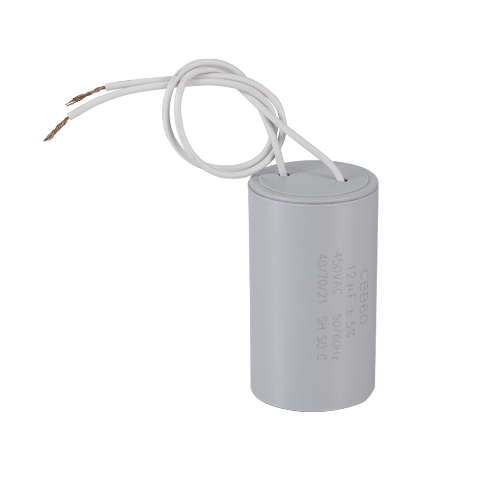


 +86-13600614158
 +86-0574-63223385
 Zonghan Street,Cixi City,Zhejiang Province,China.