
 简体中文
简体中文 English
 Español
 عربى
عربىContent
- 1 What Determines Capacitor Sizes in Practice
- 2 CBB60 Capacitor Construction and Why Its Size Scales With Capacitance
- 3 Common CBB60 Capacitor Sizes by Capacitance and Voltage
- 4 Reading a Capacitor Label Correctly
- 5 How to Select the Right Capacitor Size for a Motor
- 6 Dual-Run Capacitor Sizes for Compressor and Fan Combinations
- 7 Mounting Styles and Terminal Configurations
- 8 Temperature, Ripple Current, and Service Life
- 9 Signs a Capacitor Size Was Chosen Incorrectly
- 10 Frequently Asked Questions
- 10.1 Can I use a CBB60 capacitor with a slightly higher microfarad rating than the original?
- 10.2 Is a larger physical case always a higher microfarad value?
- 10.3 What happens if the case is too big to fit the original mounting bracket?
- 10.4 Do CBB60 capacitors need to be discharged before handling?
- 10.5 Why do two capacitors with the same uF rating sometimes weigh differently?
- 11 Why Polypropylene Film Became the Standard for CBB60 Capacitors
- 12 CBB60 Compared With Related Film Capacitor Families
- 13 Step-by-Step Installation Guidance for Correctly Sized Capacitors
- 14 Testing a Capacitor Against Its Rated Size Before Reuse
- 15 Environmental Factors That Influence Capacitor Size Choices
- 16 Storage, Shelf Life, and Bulk Purchasing Considerations
- 17 Key Terminology Reference
Quick answer: capacitor sizes are defined by three linked figures — capacitance in microfarads (uF), voltage rating in VAC, and physical case dimensions (diameter and height in mm). A CBB60 capacitor is a metallized polypropylene film run capacitor built specifically for single-phase AC motors, and its physical size grows in step with its microfarad rating because more capacitance requires more wound film inside the same construction style. Matching the correct capacitor size to a motor is not optional — an oversized or undersized unit shortens motor life, raises running current, and increases the risk of premature capacitor failure.
What Determines Capacitor Sizes in Practice
When technicians talk about "capacitor sizes," they are usually referring to two separate but connected ideas at once: the electrical size (capacitance and voltage) and the physical size (the can diameter and height that has to fit inside a motor terminal box, a compressor housing, or a fan enclosure). Both matter equally. A capacitor with the correct microfarad value but the wrong case dimensions simply will not fit in the available space, while a capacitor that physically fits but carries the wrong capacitance will not run the motor correctly.
Capacitance for motor run duty is almost always expressed in microfarads, written as uF or MFD, and typical values for residential and light commercial equipment fall between 1.5 uF and 100 uF. Larger compressors, pumps, and industrial blowers can require dual-run capacitors combining two values in one can, such as 35/5 uF or 45/7.5 uF, where the larger number serves the compressor and the smaller number serves the condenser fan motor.
Voltage rating is the second half of the sizing equation. Common ratings for motor run capacitors are 250VAC, 370VAC, and 440VAC. A 370V or 440V capacitor can generally substitute for a 250V position because the higher voltage rating gives extra safety margin, but the reverse substitution is not acceptable and will lead to dielectric breakdown under normal line voltage fluctuation.
CBB60 Capacitor Construction and Why Its Size Scales With Capacitance
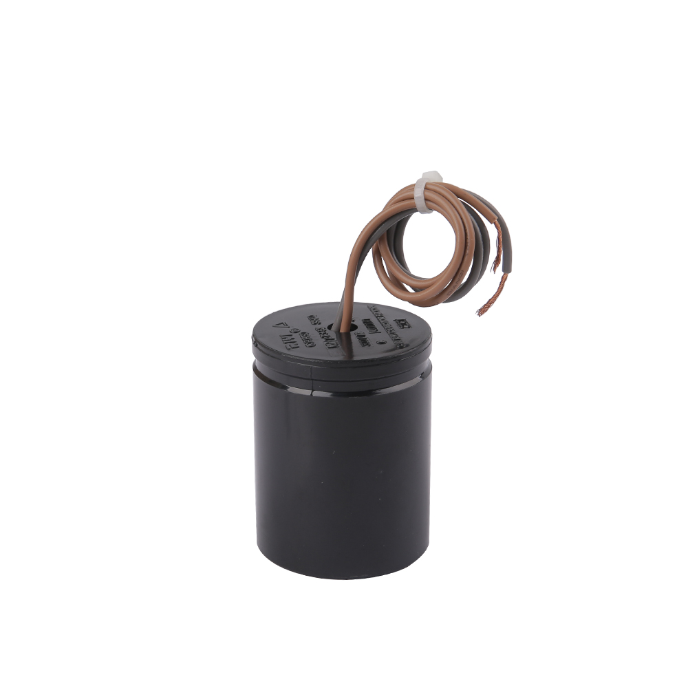
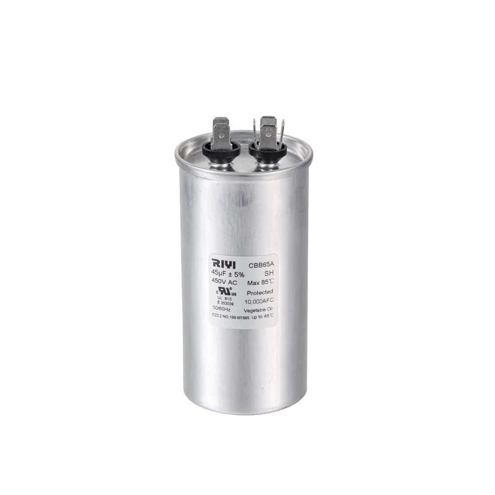
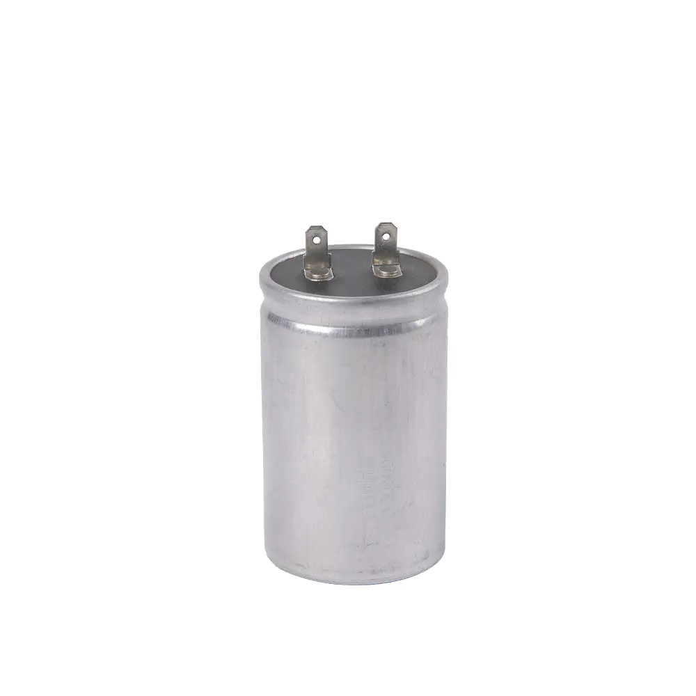
The CBB60 designation refers to a family of metallized polypropylene film capacitors housed in a round aluminum or plastic-wrapped aluminum can, typically finished in black or grey with a self-healing dielectric film. This construction style is the dominant choice worldwide for AC motor run applications including air conditioners, washing machines, water pumps, exhaust fans, and ceiling fans, largely because polypropylene film offers low dielectric loss, good self-healing behavior after minor voltage spikes, and stable capacitance across a wide temperature range.
Inside a CBB60 capacitor, capacitance is created by winding thin layers of metallized polypropylene film into a tight roll. Increasing the microfarad value means adding more film area, which physically means either a wider roll (larger diameter can) or a taller roll (taller can), or both. This is the direct engineering reason that capacitor sizes climb steadily as capacitance rises within the CBB60 family — a 1.5 uF unit can be housed in a can as small as 25mm in diameter by 45mm tall, while a 100 uF unit in the same family commonly requires a can around 50mm in diameter by 100mm or more in height.
Case Shape Options
CBB60 capacitors are manufactured in both round (cylindrical) and oval case styles. The oval body was developed specifically to fit narrow spaces inside compressor terminal boxes and rooftop condensing unit panels where a round can of the same capacitance would not clear the surrounding sheet metal. Oval units carry the same electrical rating as their round counterparts at a given capacitance and voltage, but their footprint is measured differently — width by thickness by height, rather than diameter by height.
Common CBB60 Capacitor Sizes by Capacitance and Voltage
The table below lists typical round-case CBB60 dimensions at 450VAC, the most widely stocked voltage rating for round-style motor run capacitors sold into fan, pump, and small compressor applications. Actual dimensions vary slightly between manufacturers by a few millimeters, so the physical mounting clearance should always be checked against the specific supplier's datasheet before ordering in volume.
| Capacitance (uF) | Diameter (mm) | Height (mm) | Typical Use |
|---|---|---|---|
| 2.5 | 25 | 45 | Ceiling fan, table fan |
| 6 | 30 | 50 | Exhaust fan, small water pump |
| 15 | 35 | 65 | Washing machine motor |
| 25 | 40 | 70 | Split AC condenser fan |
| 50 | 45 | 85 | Water well pump, small compressor |
| 100 | 50 | 105 | Industrial blower, large pump motor |
Reading a Capacitor Label Correctly
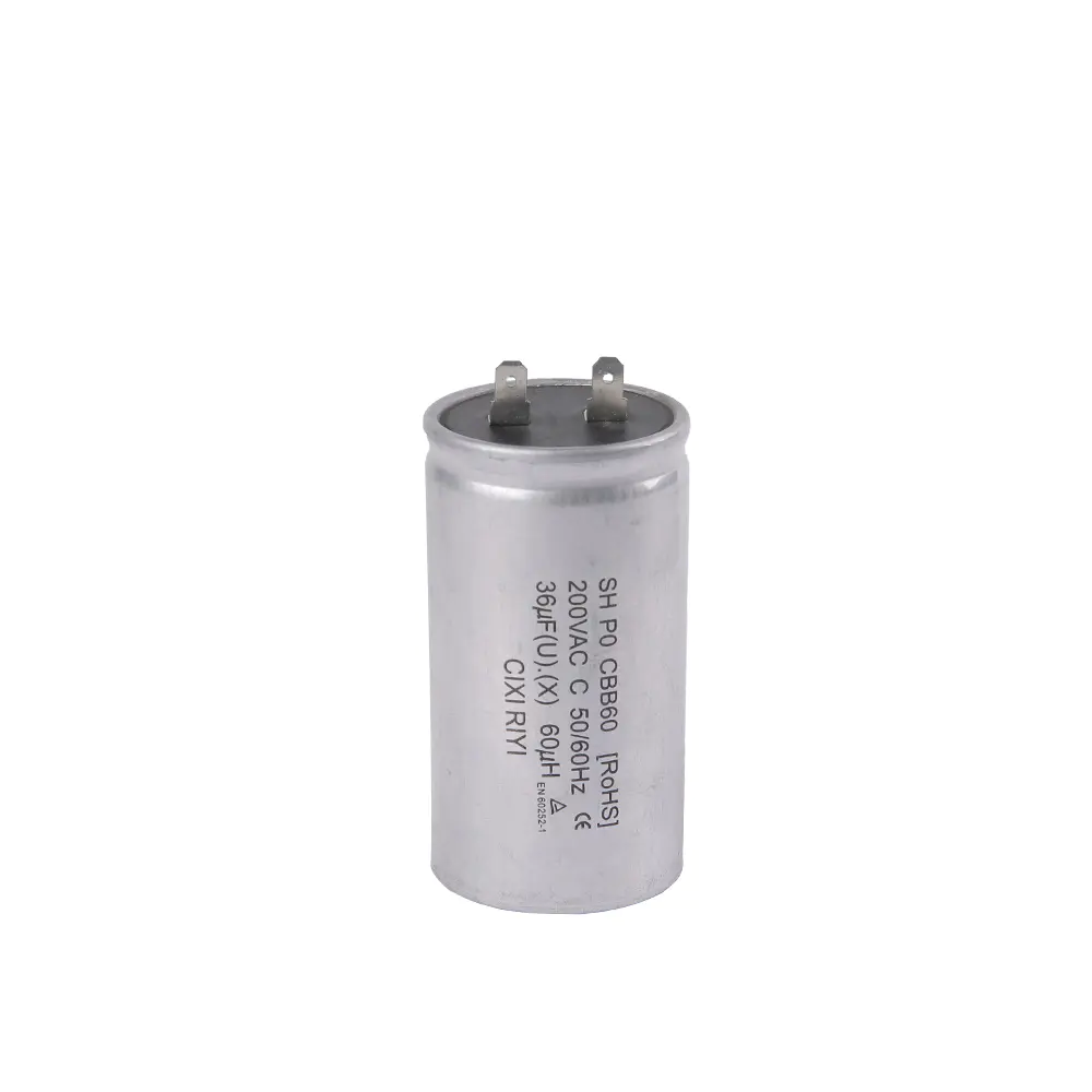
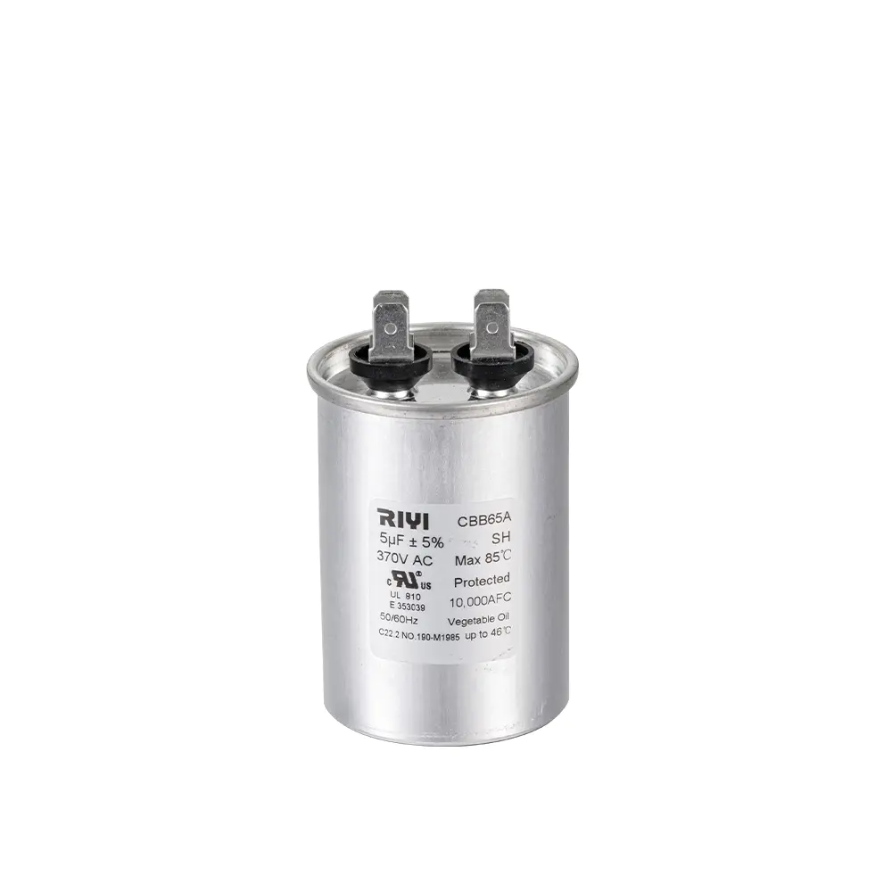
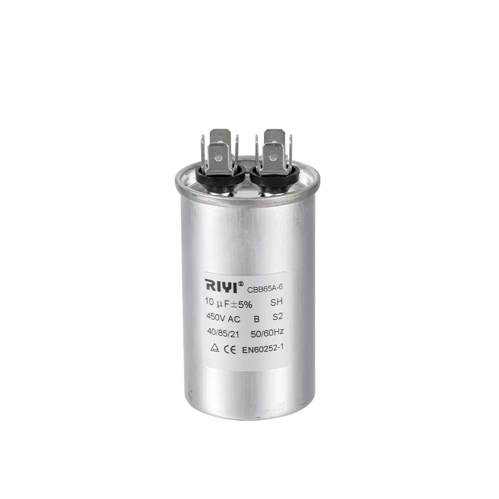
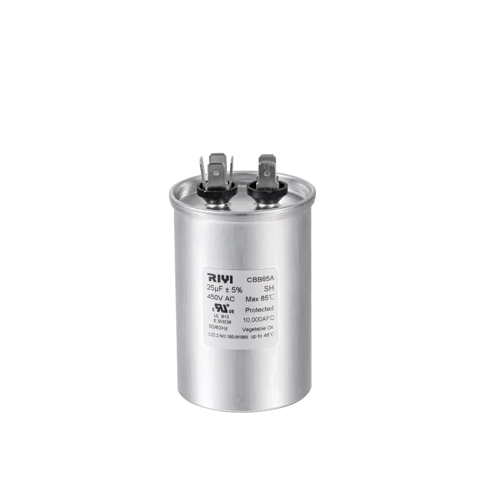
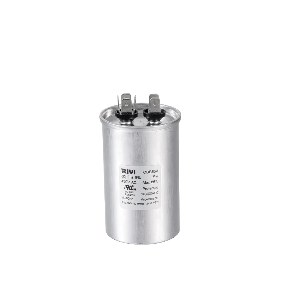
Every properly manufactured motor run capacitor prints four pieces of information directly on the can: capacitance in uF, voltage rating in VAC, an operating temperature range, and a safety/agency mark. On a CBB60 unit the label typically reads something close to "35uF 450VAC 50/60Hz" followed by a temperature code such as -25C to +70C or -40C to +85C. Reading this correctly before purchase prevents the two most common field errors: buying the wrong capacitance for the connected motor, and buying a voltage rating that is too low for the supply.
Tolerance Codes
Most CBB60 capacitors carry a tolerance of plus or minus 5 percent, marked with the letter J, though some economy lines use plus or minus 10 percent, marked K. A capacitor that has drifted more than 10 percent below its printed rating is generally considered to have failed and should be replaced rather than reused, since undersized effective capacitance causes the connected motor to draw higher running current and run measurably hotter.
How to Select the Right Capacitor Size for a Motor
Selecting capacitor size starts with the motor nameplate, not with the old capacitor, because a previously installed capacitor may already have been the wrong replacement. The nameplate microfarad value, when present, should be matched within the stated tolerance. When the nameplate does not list a capacitor value, as is common on generic fan and pump motors, sizing follows motor horsepower and voltage using standard reference ranges built up from decades of field data.
- Confirm supply voltage and motor horsepower from the nameplate.
- Match capacitance using the manufacturer's horsepower-to-microfarad chart, or the value printed on the failed unit if it matches the motor's original specification.
- Select a voltage rating equal to or higher than the original, never lower.
- Check physical clearance in the terminal box or mounting bracket before finalizing the case size.
- Verify terminal type — quick-connect spade tabs versus screw terminals — matches the existing wiring harness.
A widely used field guideline for single-phase motors is roughly 1 uF for every 25 to 35 watts of motor output at 230V supply, though this figure shifts with motor design and should always be treated as a starting estimate rather than a substitute for the manufacturer's stated value.
Dual-Run Capacitor Sizes for Compressor and Fan Combinations
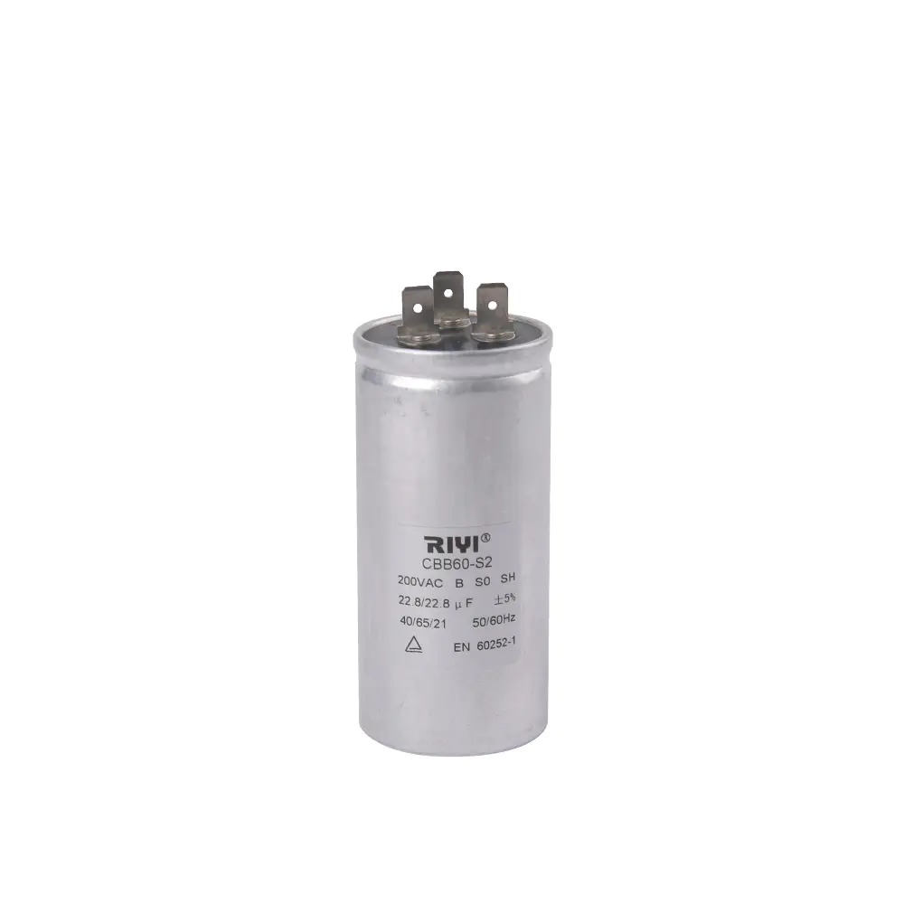
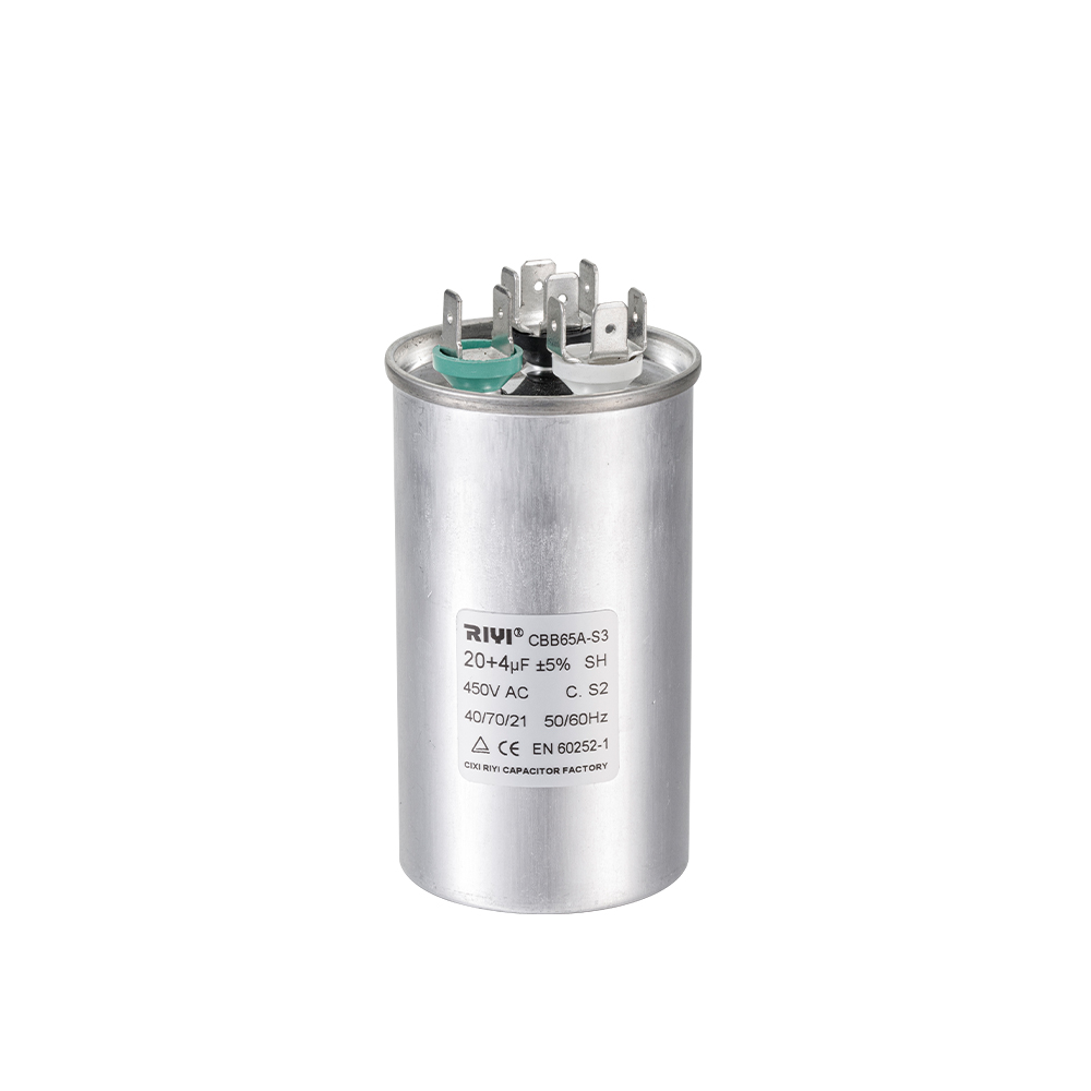
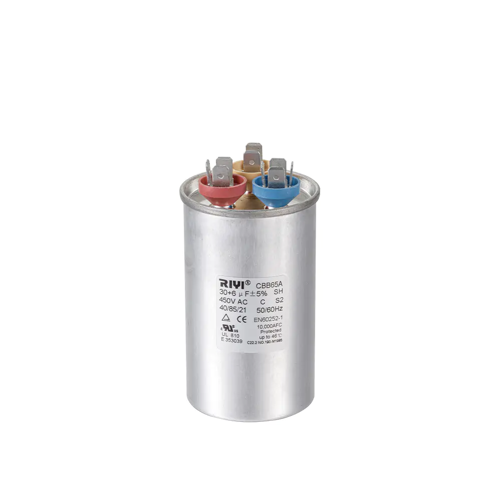
Central air conditioning and heat pump condensing units frequently use a single dual-run capacitor to serve both the compressor and the outdoor fan motor from one can. These units have three terminals marked C (common), HERM (compressor/hermetic), and FAN, and are labeled with two capacitance values, for example 40/5 uF or 55/7.5 uF. The larger figure always corresponds to the compressor circuit and the smaller figure to the fan circuit; reversing the connections does not damage the capacitor but will prevent either motor from starting correctly.
| Compressor (uF) | Fan (uF) | Approx. Case Diameter (mm) | Approx. Case Height (mm) |
|---|---|---|---|
| 25 | 3 | 45 | 75 |
| 35 | 5 | 50 | 85 |
| 45 | 7.5 | 50 | 95 |
| 55 | 7.5 | 55 | 100 |
Mounting Styles and Terminal Configurations
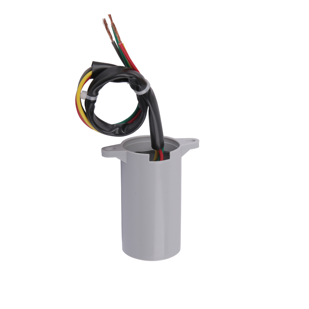
Beyond can diameter and height, capacitor size selection also involves mounting hardware compatibility. CBB60 capacitors ship with several mounting styles, and mismatching mounting style to the available bracket is one of the more common causes of field-return complaints even when the electrical rating is correct.
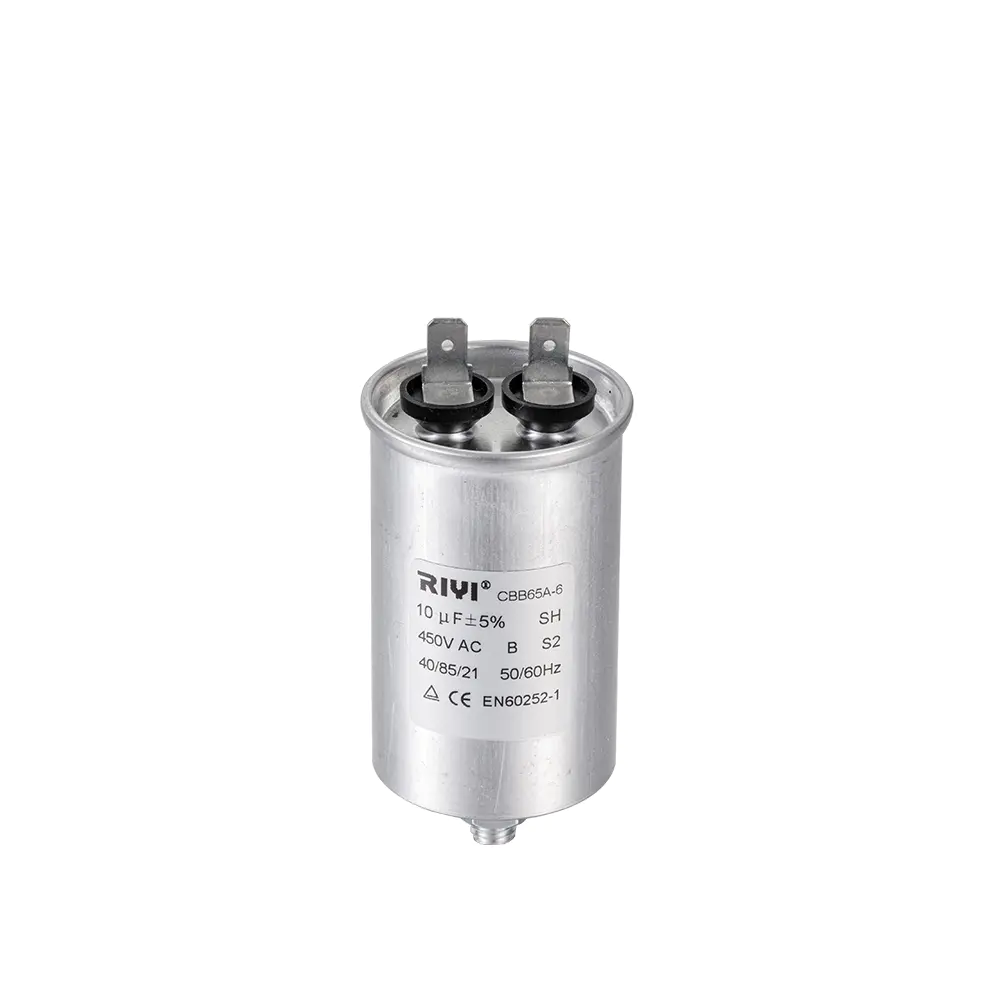
- Stud mount: a threaded stud on the base, usually 8mm or 10mm, fits into a metal bracket and is secured with a nut — common on rooftop and outdoor condensing units exposed to vibration.
- Strap mount: a metal band clamps around the can body — common on smaller fan and pump motors with limited internal space.
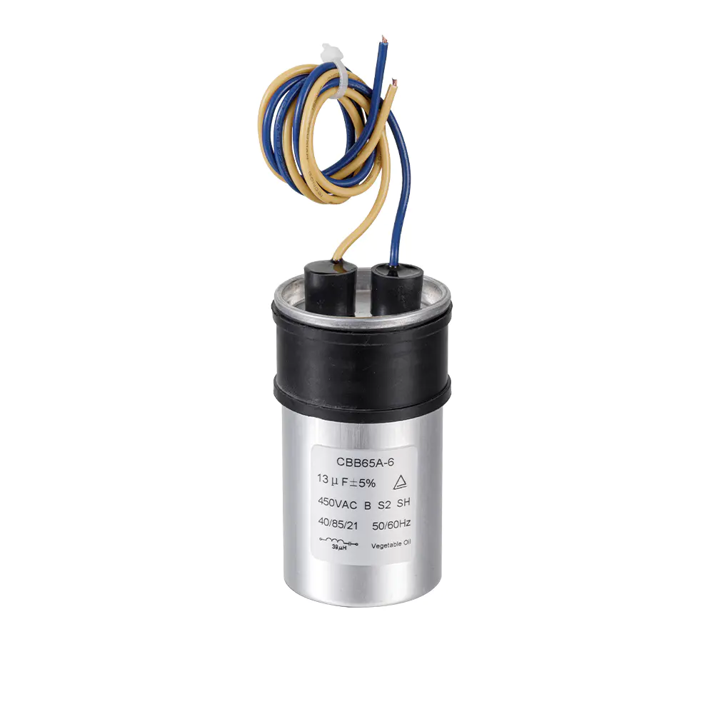
- Flying lead or spade terminal: quick-connect tabs on the top of the can for direct push-on wire connections, standard across most compact CBB60 units.
- Screw terminal: found on higher-capacitance industrial units where wire gauge is larger and a push-on tab is not adequate for the current involved.
Temperature, Ripple Current, and Service Life
Capacitor size and rated life are connected through heat. Every microfarad of film generates a small amount of internal loss under AC ripple current, and that loss must be dissipated through the can surface. A capacitor that is undersized for its application runs at a higher relative ripple current density and ages faster, while a correctly sized unit spreads that same heat load across more film surface area and lasts longer under identical duty conditions.
Manufacturer test data commonly rates CBB60 capacitors for 2,000 to 3,000 hours of continuous operation at the maximum rated temperature, with real-world service life extending to 8 to 15 years in typical residential duty cycles where the capacitor is not continuously energized at full ripple current. Ambient temperature has an outsized effect: for every 10C rise above the rated maximum, expected capacitor life is commonly estimated to fall by roughly half, which is why outdoor condensing unit capacitors mounted in direct sun tend to fail earlier than indoor units of the identical size and rating.
Signs a Capacitor Size Was Chosen Incorrectly
A capacitor that is the wrong size for its motor rarely fails silently. The symptoms below typically appear within days to a few weeks of an incorrect replacement being installed.
| Symptom | Likely Sizing Error |
|---|---|
| Motor hums but does not start | Capacitance too low for motor |
| Motor runs hot, higher amp draw | Capacitance too high for motor |
| Can bulges or vents within weeks | Voltage rating too low for supply |
| Repeated nuisance tripping on start | Wrong dual-run split between compressor and fan values |
Frequently Asked Questions
Can I use a CBB60 capacitor with a slightly higher microfarad rating than the original?
A small increase, generally within the plus or minus 5 to 10 percent tolerance band already built into most units, is acceptable. Going meaningfully above that range increases running current and motor heat, and is not recommended even though the motor may still start.
Is a larger physical case always a higher microfarad value?
Generally yes within the same manufacturer's product line and voltage rating, since more film is needed for more capacitance. However, case size also changes with voltage rating and with different manufacturers' internal winding density, so two capacitors with the same microfarad value from different suppliers can have noticeably different can dimensions.
What happens if the case is too big to fit the original mounting bracket?
An oval-case CBB60 capacitor of the same electrical rating is usually available as a direct substitute where a round can does not physically fit, and remote-mounting the capacitor with extended leads outside the original bracket is also an accepted field practice provided the leads are properly insulated and secured.
Do CBB60 capacitors need to be discharged before handling?
Yes. A run capacitor can retain a stored charge after the motor circuit is switched off, and it should be discharged across its terminals with an insulated resistor tool before it is disconnected or removed from a bracket.
Why do two capacitors with the same uF rating sometimes weigh differently?
Weight differences usually come from can material — aluminum versus a lighter resin-filled housing — and from the density of the film winding. Weight alone is not a reliable indicator of electrical performance and should not be used to judge capacitor quality.
Why Polypropylene Film Became the Standard for CBB60 Capacitors
Before polypropylene film became widely available at low cost, motor run duty was frequently served by paper-dielectric or oil-filled capacitors. Those designs carried real drawbacks: paper dielectrics absorbed moisture over time, which raised leakage current and eventually caused thermal runaway inside the can, while oil-filled units were heavier, more expensive to manufacture at scale, and posed a leakage risk if the seal degraded. Metallized polypropylene film solved most of these problems at once by offering a dielectric that is naturally resistant to moisture absorption, mechanically stable across a wide temperature swing, and self-healing after a localized dielectric breakdown.
Self-healing behavior deserves special attention because it directly affects how long a given capacitor size remains within its rated tolerance. When a microscopic weak point in the film experiences a momentary voltage spike, the extremely thin layer of vaporized metal surrounding that point burns away in a tiny, contained event, isolating the fault without materially reducing the total capacitance of the winding. A capacitor built on paper or standard oil dielectric does not have this property, so a fault in an older-style capacitor was far more likely to escalate into a full short circuit rather than a minor localized event. This is one of the underlying reasons CBB60 style construction displaced older dielectric types across nearly every motor-run application from the 1990s onward.
Metallization Thickness and Its Relationship to Capacitor Size
The thickness of the metallized layer deposited onto the polypropylene film is a variable that manufacturers tune deliberately. A thinner metallization layer improves self-healing behavior because less energy is required to vaporize the fault point, but it also raises the equivalent series resistance of the winding, which in turn raises internal heating under ripple current. A thicker metallization layer lowers resistance and heating but makes the self-healing event less contained. Reputable CBB60 manufacturers balance this tradeoff against the target voltage and capacitance rating for each specific case size, which is part of why capacitor size cannot be treated as a purely geometric calculation — the internal film specification for a 370V unit is not simply a scaled-down version of a 450V unit at the same capacitance.
CBB60 Compared With Related Film Capacitor Families
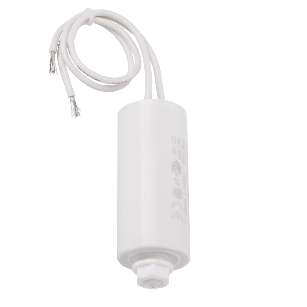
The CBB designation covers a broader family of metallized polypropylene capacitors, and buyers sourcing components for motor applications sometimes encounter adjacent part families that look similar but are engineered for different duty. Understanding these distinctions prevents a sizing or application mismatch further down the supply chain.
| Type | Typical Case | Primary Duty | Common Capacitance Range |
|---|---|---|---|
| CBB60 | Round or oval aluminum can | Continuous motor run | 1.5 to 100 uF |
| CBB61 | Flat rectangular resin block | Ceiling fan speed and run duty | 1 to 20 uF |
| CBB65 | Heavy-duty round can | Air conditioning compressor run | 15 to 60 uF |
| CBB20 | Small radial box | Audio and electronic filtering, not motor start/run | 0.001 to 10 uF |
Of these, CBB60 and CBB65 are the two families most frequently substituted for one another in the field because both are round-can, continuous-duty run capacitors. CBB65 is generally the heavier-duty designation reserved for compressor circuits that see higher ripple current, and its case size at a given capacitance is often marginally larger than an equivalent CBB60 to accommodate the additional thermal margin.
Step-by-Step Installation Guidance for Correctly Sized Capacitors
Even a correctly sized capacitor can be rendered ineffective, or dangerous, by poor installation practice. The sequence below reflects standard field practice used across HVAC, pump, and general motor service work.
- Disconnect power at the breaker or disconnect switch and verify zero voltage with a meter before touching any wiring.
- Discharge the existing capacitor across its terminals using an insulated discharge tool, even if the unit is suspected of already being dead, since a partially failed capacitor can still hold a dangerous charge.
- Photograph or label the existing wiring before disconnecting, particularly on dual-run capacitors where the C, HERM, and FAN terminals must be reconnected to the correct new terminal.
- Remove the old capacitor from its mounting bracket or strap and confirm the replacement matches capacitance, voltage rating, and terminal layout before inserting it.
- Secure the new capacitor in its bracket so that vibration during motor operation cannot loosen the terminal connections over time.
- Reconnect wiring exactly as labeled, restore power, and observe motor start and run behavior for at least one full duty cycle before closing up the enclosure.
Orientation and Clearance Considerations
Capacitor size interacts with installation orientation in ways that are easy to overlook. Vertically mounted round capacitors should generally be installed with the vent or pressure-relief feature on the top of the can facing upward and unobstructed, since this feature is designed to release internal pressure safely if the unit fails, and blocking it with wiring or an enclosure panel defeats that safety function. Horizontally mounted units need enough radial clearance around the vent area to allow the same safe release path, which becomes a tighter constraint as case diameter increases with higher capacitance.
Testing a Capacitor Against Its Rated Size Before Reuse
Field technicians routinely test a suspect capacitor before condemning it, since a capacitor that appears to be the wrong size or rating on the label is not always actually faulty, and conversely a capacitor that looks physically intact can have drifted well outside its rated tolerance. A digital multimeter with a dedicated capacitance range, or a purpose-built capacitor tester, is the standard tool for this check.
| Measured Value vs Rated uF | Interpretation |
|---|---|
| Within plus or minus 5 to 10 percent | Capacitor is within normal tolerance and can remain in service |
| 10 to 20 percent below rating | Early degradation; monitor closely or plan replacement |
| More than 20 percent below rating | Replace immediately, motor is at risk of hard-starting or overheating |
| Zero or open reading | Internal winding has failed open, capacitor must be replaced |
A meter reading noticeably above the rated value, rather than below it, is less common but can indicate an internal short across part of the winding, which behaves electrically as added capacitance right up until the point of full failure. Any reading that deviates meaningfully in either direction should be treated as grounds for replacement rather than continued service.
Environmental Factors That Influence Capacitor Size Choices
Selecting a capacitor size is not purely an electrical exercise once the installation environment is factored in. Outdoor condensing units, rooftop equipment, and marine or coastal installations all place additional demands on the physical case that go beyond the base electrical rating.
High Ambient Temperature Locations
In regions where outdoor ambient temperatures regularly exceed 40C, specifying a capacitor one physical size class larger than the strict electrical minimum is a common engineering practice, since the larger film surface area lowers the operating temperature rise relative to a tightly sized unit and directly extends expected service life under sustained heat load.
Humid and Coastal Environments
Salt-laden air accelerates corrosion of the aluminum can and terminal hardware, which can compromise the seal integrity that protects the internal film winding from moisture ingress. Capacitors specified for coastal or marine duty commonly use a resin-coated or fully plastic-jacketed can construction rather than bare aluminum, and this coating adds a small amount to the overall case dimensions that should be accounted for when confirming mounting clearance.
Vibration-Heavy Installations
Motors mounted on vibrating platforms, including some agricultural pump and industrial fan installations, benefit from stud-mount capacitors secured with a locking washer rather than strap-mount units, since sustained vibration can gradually loosen a strap clamp and allow the capacitor body to move against its terminal leads, eventually fatiguing the lead wire at the point it exits the can.
Storage, Shelf Life, and Bulk Purchasing Considerations
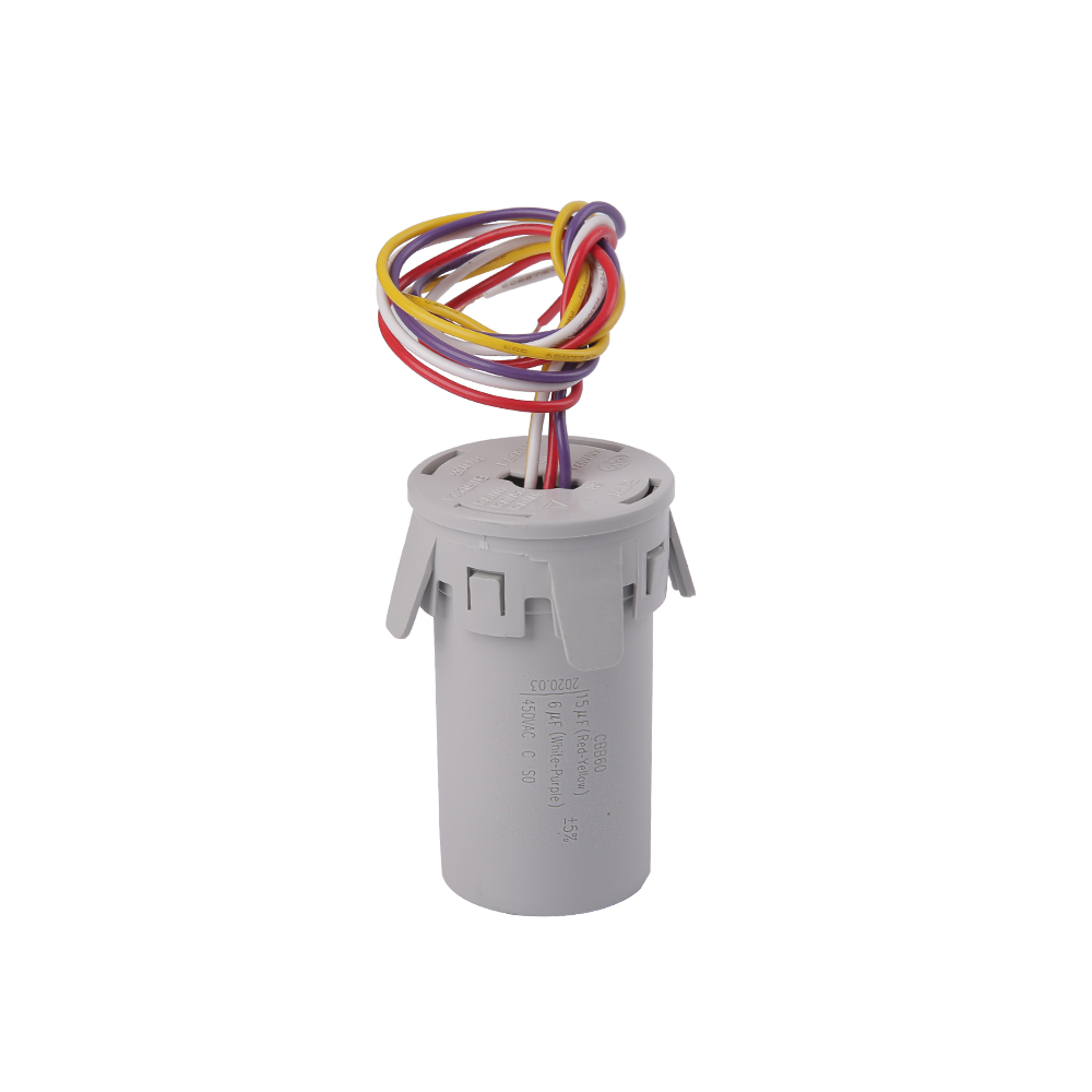
Buyers sourcing CBB60 capacitors in volume for equipment manufacturing or wholesale distribution should account for storage conditions as part of the overall size and inventory planning process. Unlike electrolytic capacitors, metallized polypropylene film units do not require periodic reforming and have a long, stable shelf life when stored correctly, but poor storage practice can still degrade performance before the capacitor ever reaches installation.
- Store in a dry environment with relative humidity below roughly 75 percent to prevent moisture migration at the terminal seals.
- Keep stock away from direct sunlight and away from heat sources such as radiators or exterior warehouse walls exposed to full sun.
- Organize inventory by capacitance and case size together, since two boxes of visually similar capacitors with different microfarad ratings are a common source of picking errors on a busy production line.
- Rotate older stock first, particularly for higher-capacitance units where film winding density is greater and any slow moisture ingress has a proportionally larger surface area to act on.
For bulk purchasing decisions, buyers frequently standardize on a smaller number of case sizes covering the most common capacitance and voltage combinations used across a product line, rather than stocking every intermediate value. This approach trades a small amount of over-specification on lower-demand motors for meaningfully simplified inventory management, fewer stock-keeping units, and stronger per-unit pricing from the manufacturer at higher order volumes.
Key Terminology Reference
| Term | Meaning |
|---|---|
| MFD | Older abbreviation for microfarad, still printed on many capacitor labels alongside or instead of uF |
| VAC | Volts of alternating current, the voltage rating the capacitor is designed to withstand continuously |
| Ripple current | The alternating current that flows through the capacitor during normal motor operation, the primary source of internal heating |
| Dielectric | The insulating film layer, polypropylene in a CBB60, that separates the metallized conductive layers |
| Self-healing | The property of metallized film that isolates a localized dielectric fault without a full short circuit |
| Pressure relief vent | A scored or embossed section of the can top designed to open safely if internal pressure builds during failure |
| Dual-run capacitor | A single can housing two separate capacitance values sharing a common terminal, typically for compressor and fan |

 +86-13600614158
 +86-0574-63223385
 Zonghan Street,Cixi City,Zhejiang Province,China.