 简体中文
简体中文 English
 Español
 عربى
عربىContent
- 1 The Direct Answer: How a CBB60 Capacitor Connects
- 2 Why the CBB60 Capacitor Exists in the Circuit
- 3 Tools and Materials to Gather Before Starting
- 4 Step-by-Step Connection Procedure for a Pump Motor
- 4.1 Step 1 — Cut Power and Confirm Zero Voltage
- 4.2 Step 2 — Discharge the Existing Capacitor
- 4.3 Step 3 — Document the Existing Wiring
- 4.4 Step 4 — Remove the Old Capacitor
- 4.5 Step 5 — Identify the Motor Terminals
- 4.6 Step 6 — Make the CBB60 Connections
- 4.7 Step 7 — Mount the Capacitor Securely
- 4.8 Step 8 — Restore Power and Test Operation
- 5 Wiring the CBB60 in an External Capacitor Enclosure
- 6 CBB60 Connection Configurations Across Different Motor Types
- 7 Reading the Motor Wiring Diagram to Find the Right Terminals
- 8 Critical Wiring Mistakes and Their Consequences
- 9 Verifying the CBB60 Connection Is Correct After Power-Up
- 10 Selecting the Right Replacement CBB60 Before Making Any Connections
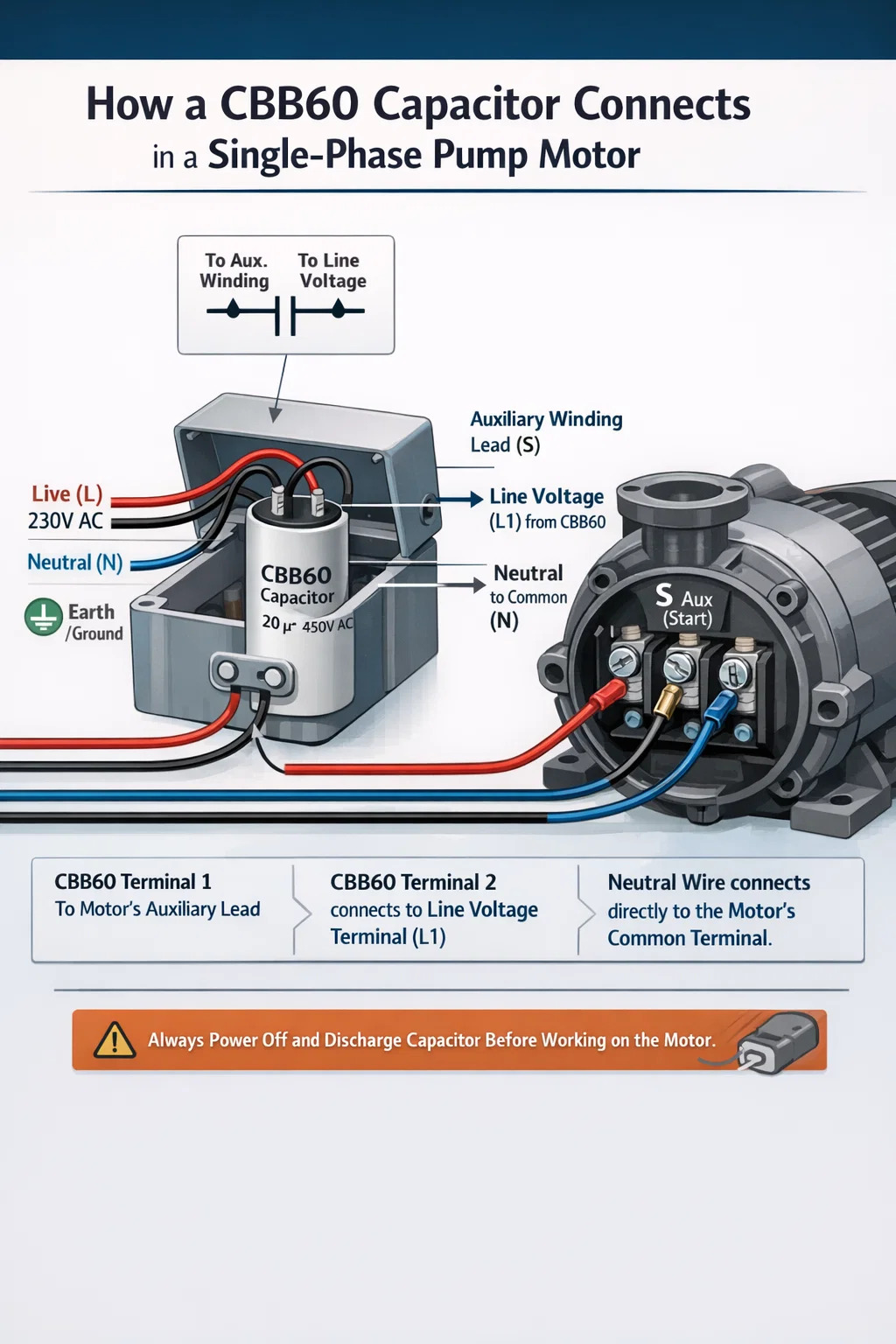
The Direct Answer: How a CBB60 Capacitor Connects
A CBB60 capacitor connects in parallel across the motor's auxiliary (run) winding — not in series with the main power line. Its two terminals are non-polarized, so there is no positive or negative side to worry about. One terminal goes to the motor's auxiliary winding lead, and the other connects to the line voltage terminal (the same point that feeds the main winding). This creates the phase shift the motor needs to generate torque and run efficiently.
For the most common scenario — a single-phase pump motor with an external capacitor box — the incoming live wire and the motor's auxiliary lead both land on the CBB60, while neutral connects directly to the motor's common terminal. The motor runs because current through the capacitor leads the supply voltage by roughly 90 degrees, producing the rotating magnetic field that a single-phase supply alone cannot create.
Before touching any wiring, shut off the circuit breaker, confirm zero voltage at the motor terminals with a multimeter, and discharge the capacitor through a 20,000-ohm resistor. A charged CBB60 rated at 450 VAC can hold lethal voltage for hours after power is removed.
Why the CBB60 Capacitor Exists in the Circuit
Single-phase AC motors cannot self-start. A single-phase supply produces a pulsating magnetic field that reverses direction 100 or 120 times per second (depending on 50 Hz or 60 Hz grid frequency) but has no inherent rotation. To make the rotor spin, the motor needs two magnetic fields displaced in both space and time — effectively simulating two-phase power.
The CBB60 run capacitor provides the time displacement. Because current through a capacitor leads the voltage across it by approximately 90 degrees, the current in the auxiliary winding is out of phase with the current in the main winding. These two offset currents create two spatially separated magnetic fields that together produce a rotating effect, pulling the rotor into motion and sustaining it throughout operation.
Unlike a start capacitor — which is switched out of the circuit by a centrifugal switch once the motor reaches roughly 75% of rated speed — the CBB60 stays connected continuously during running. This is why it uses metalized polypropylene film construction rather than electrolytic chemistry: it must tolerate continuous AC voltage without degrading. Common CBB60 ratings for pump motors span 6 µF to 100 µF, with voltage ratings of 250 VAC or 450 VAC.
Tools and Materials to Gather Before Starting
Having the right equipment on hand before starting prevents mid-job improvisation that leads to unsafe shortcuts.
- Digital multimeter with AC voltage and capacitance (µF) measurement functions
- Discharge resistor: 20,000 ohms (20 kΩ) rated at 5W or higher, with insulated leads
- Insulated screwdrivers (flathead and Phillips)
- Wire stripper and ratcheting crimping tool
- Spade connectors sized to fit the CBB60 terminals (typically 6.3 mm female spade)
- Electrical tape or adhesive heat-shrink tubing
- Clamp ammeter (for post-installation current verification)
- The motor's wiring diagram — printed on the nameplate label, inside the terminal cover, or in the motor documentation
- Rubber-soled footwear and voltage-rated insulated gloves
- Lockout/tagout device for the circuit breaker if working in a shared or commercial environment
Photograph the existing wiring from at least two angles before removing anything. In crowded junction boxes or external capacitor enclosures, this photo is worth far more than trying to reconstruct the wiring from memory.
Step-by-Step Connection Procedure for a Pump Motor
This procedure covers the most common CBB60 installation: a single-phase water pump or pool pump motor, either with an external capacitor enclosure or with the capacitor directly inside the motor's terminal box. The same logic applies to air compressors, washing machines, and HVAC fan motors.
Step 1 — Cut Power and Confirm Zero Voltage
Switch off the circuit breaker feeding the motor. Apply a lockout device if available. Set the multimeter to AC voltage and probe the motor's input terminals. The reading must be 0 V before proceeding. Do not rely on a switch or timer being in the off position — verify with the meter directly.
Step 2 — Discharge the Existing Capacitor
Hold the discharge resistor by its insulated body. Touch one lead to each of the capacitor's terminals simultaneously and hold for a minimum of 5 seconds. Then probe across the terminals with the multimeter set to DC voltage — confirm the reading is at or near 0 V before removing any wires or touching the terminals directly.
Step 3 — Document the Existing Wiring
Take clear photographs. If wire colors are ambiguous or multiple wires share a terminal, apply small masking tape labels to each wire before removing anything. Note which wires were connected to each capacitor terminal and where the other ends of those wires go in the circuit.
Step 4 — Remove the Old Capacitor
Pull the spade connectors off the capacitor terminals. If they are corroded and resist removal, use insulated pliers to grip the connector body — never pull by the wire itself, as this can break the crimp. Unscrew or unclip the mounting bracket and remove the old capacitor. Set it aside; do not short its terminals together or place it loose in a metal toolbox.
Step 5 — Identify the Motor Terminals
Locate the motor's terminal block and match the labels to the wiring diagram. For a three-wire motor (most common configuration), the terminals are:
- Common (C): Shared connection between main and auxiliary windings; connects to neutral
- Main (M or R): Free end of the main winding; connects to line voltage
- Start/Run (S): Free end of the auxiliary winding; connects to one terminal of the CBB60
If the terminal labels are missing or illegible, identify them by resistance measurement. Measure resistance between all three wire pairs. The pair with the highest resistance is M–S (both windings in series). The pair with the lowest resistance is C–M (main winding alone, heavier wire). The intermediate resistance is C–S (auxiliary winding alone). The wire common to the two lowest readings is C.
Step 6 — Make the CBB60 Connections
The standard connection for a capacitor-run single-phase motor:
- CBB60 Terminal 1 → Motor's auxiliary winding terminal (S or Z1)
- CBB60 Terminal 2 → Line voltage terminal (L1, same terminal that feeds the main winding)
- Neutral (N) → Motor's Common (C) terminal directly, not through the capacitor
Crimp fresh spade connectors onto the wire ends if the old ones are corroded or deformed. Push each spade connector fully onto its capacitor terminal until it seats with a click or firm resistance. A connector that can be removed with light finger pressure is not properly seated.
Step 7 — Mount the Capacitor Securely
Fasten the CBB60 into its bracket or strap so it cannot vibrate freely. Motor vibration transmitted to an unsupported capacitor fatigues the internal lead connections over time, eventually producing an open-circuit failure. Ensure the capacitor body does not contact any hot motor surfaces, sharp metal edges, or moving parts such as fan blades or belt drives.
Step 8 — Restore Power and Test Operation
Replace the terminal cover or close the capacitor enclosure. Restore power at the breaker and observe the motor start. It should reach full speed within 1 to 3 seconds with no hesitation, humming, or repeated attempts. For a pump, water flow should begin promptly. If the motor hums without spinning, cut power immediately — it is drawing locked-rotor current (typically 5 to 7 times normal running current) and will overheat and damage the windings within 20 to 30 seconds.
Wiring the CBB60 in an External Capacitor Enclosure
Many single-phase pump motors — particularly surface pumps, peripheral pumps, and submersible pump control boxes — mount the CBB60 in a separate plastic or metal enclosure rather than inside the motor's own terminal box. This arrangement simplifies capacitor replacement and protects the component from motor heat.
The external enclosure typically has four terminals or two pairs of wire entry points. The wiring inside follows this arrangement:
- Mains live (L) enters the enclosure and connects to one CBB60 terminal and also passes through to the motor's main winding lead
- The motor's auxiliary winding lead connects to the other CBB60 terminal inside the enclosure
- Mains neutral (N) passes directly through to the motor's common terminal without touching the capacitor
- Earth/ground connects to the motor frame and does not interact with the capacitor circuit
When the enclosure is a sealed or semi-sealed unit sold as a complete assembly, the CBB60 inside it is pre-wired and the installer only connects the mains supply cables and the motor flying leads to the external terminals of the box. In this case, the only decision is ensuring the replacement CBB60 installed inside the box matches the original specification exactly.
Some external boxes accommodate a specific physical capacitor size and terminal spacing. Measure the original unit's dimensions — height, diameter (for round housings), and terminal spacing — before ordering a replacement. A CBB60 with correct electrical ratings but wrong physical dimensions may not fit the mounting bracket even if the wiring would be identical.
CBB60 Connection Configurations Across Different Motor Types
The terminal labels and physical arrangement differ between motor manufacturers and applications, but the underlying circuit relationship is always the same: the CBB60 bridges the auxiliary winding path in parallel. The table below maps the most common configurations.
| Motor / Application | CBB60 Terminal A Connects To | CBB60 Terminal B Connects To | Neutral Goes To |
|---|---|---|---|
| Single-phase pump (3-wire) | Start terminal (S) | Line voltage / Main terminal (M) | Common terminal (C) |
| IEC-labelled motor (4-wire) | Auxiliary winding Z1 | Z2 (or line terminal U1) | U2 or neutral terminal |
| Air compressor motor | Start winding lead | Common winding terminal | Neutral input terminal |
| Pool / spa pump motor | Auxiliary winding lead | Line input (L1 — 230 V) | Motor common / neutral |
| Washing machine motor | Run winding terminal | Auxiliary winding terminal | Common through direction switch |
| External capacitor box (pump) | Motor auxiliary flying lead | Mains live (L) inside box | Motor common flying lead |
Reading the Motor Wiring Diagram to Find the Right Terminals
The motor wiring diagram removes guesswork entirely. It is printed on a label stuck to the motor housing, inside the terminal box lid, or on a separate datasheet. Learning to extract the two pieces of information you need — where the auxiliary winding ends are and which terminal carries line voltage — takes less than a minute once you know the symbols.
Capacitor Symbol on Motor Diagrams
The CBB60 is shown as two parallel vertical lines of equal size (non-polarized AC type). One line of the symbol connects to the auxiliary winding coil symbol; the other line connects to the line voltage path. Follow these two connection points on the diagram to the physical terminal labels on the motor, and those are your two CBB60 connection points.
Terminal Label Systems by Region
- IEC / European: Main winding terminals U1, U2; auxiliary winding terminals Z1, Z2. CBB60 connects across Z1 and Z2 (or Z1 to U1 in some configurations)
- North American: Terminals labeled T1, T2, T3 or named Common, Run, Start. CBB60 connects between Run and Start (or Start and line voltage)
- Chinese pump motors (most CBB60 applications): Color-coded wires rather than labeled terminals. Black = main winding, Red = auxiliary winding, Yellow-Green = earth. CBB60 connects between the red wire and the black wire (line side)
Finding Terminals Without a Diagram Using Resistance Measurement
On a three-wire motor with no available diagram, use the multimeter in ohms mode to measure resistance between all three wire combinations:
- Record all three readings: A–B, A–C, B–C
- The highest resistance pair is Main–Start (both windings in series). Example: 23 Ω
- The lowest resistance pair is Common–Main (main winding only, thicker wire). Example: 8 Ω
- The middle resistance pair is Common–Start (auxiliary winding only, thinner wire). Example: 15 Ω
- The wire appearing in both the lowest and middle readings is Common (C)
- CBB60 connects between Start (S) and the line terminal (the same wire as Main's supply point)
This method works reliably on any standard capacitor-run single-phase motor regardless of labeling, age, or country of manufacture.
Critical Wiring Mistakes and Their Consequences
Each of the following errors produces a predictable and diagnosable outcome. Knowing them in advance prevents rework, protects the motor, and avoids safety hazards.
Connecting the CBB60 in Series with the Power Line
Placing the capacitor between the mains supply and the motor input — rather than across the auxiliary winding — limits the current the motor can draw through the capacitor's impedance. At 50 Hz, a 25 µF capacitor has an impedance of roughly 127 ohms, which at 230 V limits current to under 1.8 A. A typical 750 W pump motor requires 3 to 4 A to run. The motor will not start or will stall under any meaningful load, and the capacitor will experience current stress outside its design parameters.
Using the Wrong Capacitance Value
Motor designers calculate the required capacitance precisely for each winding configuration. A CBB60 20% below rated capacitance reduces starting torque noticeably and causes the motor to run hotter than specified. A capacitor 20% above rated value causes excessive current through the auxiliary winding, overheating it and degrading winding insulation faster than normal. Always match the µF value exactly, or stay within ±5% of the motor nameplate specification.
Under-Rated Voltage
A 250 VAC rated CBB60 in a 230 V system has only a 9% voltage margin above nominal supply. Grid voltage fluctuations of ±10% are standard in most countries. During a high-voltage event, the capacitor may see 253 V — already above its rating. Install a 450 VAC rated CBB60 in any 230 V application to ensure adequate margin against both normal voltage variation and transient spikes.
Loose Spade Connector Fit
A spade connector that is not fully seated on the CBB60 terminal introduces contact resistance at the junction. Under load current, this resistance generates heat that oxidizes the contact surfaces, further increasing resistance in a destructive cycle. The eventual result is either intermittent motor starting behavior or a burned connector. Every spade should require firm hand pressure to seat and should not be removable by gentle tugging without a tool.
Skipping Capacitor Discharge
A CBB60 rated at 450 VAC can retain a charge approaching that voltage for hours after the power is disconnected. The energy stored in a 40 µF capacitor charged to 400 V is 3.2 joules — enough to cause a severe burn or cardiac event if contacted across the chest. Never touch capacitor terminals, allow them to contact each other, or allow tools to bridge them without first completing the discharge procedure with the resistor and verifying 0 V with the multimeter.
Verifying the CBB60 Connection Is Correct After Power-Up
Three quick checks after restoring power confirm the installation is electrically correct and the motor is performing within specification.
Check 1 — Clean Motor Start
The motor should accelerate from standstill to full speed in 1 to 3 seconds with no audible humming, hesitation, or grinding. A hum with no shaft rotation means the motor is locked — cut power within 5 seconds to prevent winding damage and recheck the wiring.
Check 2 — Running Current Within Nameplate Rating
Clamp the ammeter around the live wire and measure running current after 2 to 3 minutes of operation under load. The reading should be at or below the full-load amperage (FLA) on the motor nameplate. A reading more than 10% above nameplate FLA under normal load conditions points to a capacitance mismatch or wiring error that should be investigated before continuing operation.
Check 3 — Voltage Across CBB60 Terminals While Running
With the motor running, carefully measure AC voltage across the two CBB60 terminals using the multimeter set to AC voltage. In a correctly wired capacitor-run motor, this voltage is typically 1.1 to 1.5 times the supply voltage — for a 230 V supply, expect to read 250 to 340 V across the capacitor terminals. This is normal: it results from the resonant interaction between the capacitor and the motor winding inductance. A reading exactly equal to or lower than supply voltage may indicate the capacitor is not actually in the circuit or is wired incorrectly.
Selecting the Right Replacement CBB60 Before Making Any Connections
Connecting a CBB60 correctly is straightforward. Connecting the wrong CBB60 correctly still produces a failing or underperforming motor. Confirm these parameters on the replacement unit before installation.
style="display: table-cell; border: 1px solid #cccccc; padding: 8px;">Shortened service life in hot locations| Parameter | Where to Find It | Acceptable Range | Consequence of Mismatch |
|---|---|---|---|
| Capacitance (µF) | Capacitor label and motor nameplate | Exact match, ±5% | Reduced torque or overheating |
| Voltage rating (VAC) | Capacitor label | Equal or higher only | Premature dielectric failure |
| Frequency (Hz) | Capacitor label | Must match grid (50 or 60 Hz) | Incorrect phase angle, heating |
| Temperature rating | Capacitor label (70°C, 85°C, 105°C) | Equal or higher | |
| Physical size and terminal spacing | Measure original unit in mm | Must fit existing bracket | Cannot install; vibration damage if loose |
For any 230 V pump or compressor application, the practical recommendation is a CBB60 rated at the correct capacitance with a 450 VAC voltage rating and 85°C or higher temperature rating. This combination provides the voltage margin and thermal headroom that the common 250 VAC / 70°C specification does not, particularly for outdoor or high-duty-cycle installations where ambient temperatures frequently exceed 40°C around the motor enclosure.


 +86-13600614158
 +86-0574-63223385
 Zonghan Street,Cixi City,Zhejiang Province,China.